Introduction
The purpose of this study was to analyze displacement and stress distribution in the maxilla during maxillary expansion followed by protraction using bone-borne and conventional tooth-borne palatal expanders and a facemask via 3-dimensional finite element analysis.
Methods
A finite element model of an adolescent skull was created, and 4 different types of appliances were integrated into it: facemask (type A); facemask with paramedian bone-borne expander (type B), facemask with palatal-slope bone-borne expander (type C), and facemask with conventional expander (type D). Expansion of 0.25 mm followed by 500 g of force per side was applied.
Results
Type A showed anterior displacement of the dentition combined with downward displacement of posterior teeth and upward displacement of anterior teeth. The combination of protraction and expansion in type D showed the greatest anterior displacement. In types B and C, the expansion forces resulted in posterior displacement decreasing the net displacement of the combination. Stresses concentrated around the miniscrews in types B and C. In types A and D, stresses concentrated at the first premolar and first molar. Type B had the highest stresses followed by type C and then D.
Conclusions
The conventional tooth-borne expander (type D) enhanced the effect of maxillary protraction. Facemask alone (type A) resulted in more anterior displacement of the maxilla than the combination of facemask and bone-borne expanders (types B and C). The clinician should be aware of the initial stresses and movements from different expanders with facemask found in this study and confirm the movements in future clinical Class III studies.
Highlights
- •
Maxillary expansion with bone-borne and tooth-borne expanders was analyzed.
- •
Bone-borne expansion produced posterior displacement and decreased net displacement.
- •
Stresses concentrated around the miniscrews.
- •
Tooth-borne expansion enhanced the effect of maxillary protraction.
- •
The facemask alone produced more anterior displacement of the maxilla.
Early intervention treatment of growing Class III patients is still challenging to clinicians. Maxillary protraction using a facemask (FM) has been the treatment of choice. Recent application of skeletal anchorage devices has introduced a new paradigm to avoid surgery in some skeletal Class III patients.
Since maxillary deficiency is usually combined with transverse discrepancy, rapid palatal expansion becomes an essential treatment modality for those patients. However, tooth-borne palatal expansion achieves skeletal expansion with the side effect of dental expansion that may lead to root resorption of the posterior teeth or gingival recession. Therefore, several skeletal anchorage systems have been proposed to maximize the skeletal effect of maxillary expansion and decrease the undesirable dental effects in adolescents.
Traditionally, FM with rapid palatal expansion has shown significantly favorable skeletal and dental changes when used to treat children with Class III malocclusion. Recently, this combination has been applied in adolescent and adult patients for nonextraction treatment of Class III patients. The effectiveness and efficiency of different combinations of protraction and expansion treatment modalities have been reported. Maxillary protraction produced more anterior displacement of the maxilla with decreased upward-forward rotation when it was combined with palatal expansion. On the other hand, Vaughn et al reported that FM therapy with or without tooth-borne palatal expansion produced equivalent changes in the dentofacial complex and suggested that the indication for palatal expansion should be based on clinical criteria other than assisting Class III correction.
Three-dimensional finite element (FE) analysis provides a reliable method that can explain the effect of the combination of FM and rapid palatal expansion. It has been applied extensively to evaluate the treatment effects of maxillary protraction in the maxillofacial complex. However, no study has evaluated the effects of the addition of a bone-borne palatal expander on the FM treatment effect.
Therefore, the aim of this study was to analyze the displacement and stress distribution in the maxilla during maxillary expansion using bone-borne and conventional tooth-borne palatal expanders followed by protraction with a FM via 3-dimensional FE analysis.
Material and methods
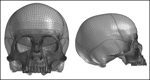
The FE model was created from tomography images of a dry skull of an adolescent using Mimics software (version 15.01; Materialise, Leuven, Belgium). Visual-mesh software (version 7.0; ESI Group, Paris, France) was used to produce a tetrahedral FE mesh. The maxilla, dentition, and alveolar bone in the FE mesh were sectioned into 1-mm tetrahedrons. The remaining skull bones including their sutures were sectioned into 5-mm tetrahedrons. The model consisted of 1088171 elements and 226458 nodes ( Fig 1 ). The dentition, alveolar bone, and periodontal ligament were considered homogenous and isotropic. The thickness of the periodontal ligament was considered to be 0.2 mm, and the thickness of the midpalatal sutures was considered to be 0.5 mm. All circumaxillary sutures were modeled with a width of approximately 0.5 mm divided into 2 layers. Thus, the size of the suture mesh along its thickness was 0.25 mm with an aspect ratio 0.25. The thickness of cortical bone was determined according to the study of Farnsworth et al. The mechanical properties of the different structures of the model are shown in Table I .
| Material | Young’s modulus (MPa) | Poisson’s ratio |
|---|---|---|
| Cortical bone | 1.37 × 10 4 | 0.30 |
| Cancellous bone | 7.90 × 10 3 | 0.30 |
| Stainless steel wire | 2.00 × 10 5 | 0.30 |
| Miniscrew | 1.05 × 10 5 | 0.33 |
| Acrylic button | 2.30 × 10 4 | 0.40 |
| Tooth | 2.07 × 10 4 | 0.30 |
| Periodontal ligament | 50.00 | 0.49 |
| Suture | 1.00 | 0.40 |
Foramen magnum was fixed and set as the origin point. The forehead was in contact with a fixed band to mimic the effect of the FM. The 3-dimensional coordinates were x (anteroposterior plane), y (transverse plane), and z (vertical plane). Positive values for x, y, and z indicated forward, outward, and upward displacements.
Four models were made: FM with labiolingual appliance (type A), FM with bone-borne expander supported by 4 miniscrews (C-implants; Cimplant, Seoul, Korea) with a diameter of 1.8 mm and a length of 8.5 mm placed in the paramedian area (type B), FM with bone-borne expander supported by 4 miniscrews placed in the palatal slopes (type C), and FM with conventional hyrax expander (type D). Each rapid palatal expansion appliance had an expansion screw for 0.25 mm of widening per turn ( Figs 2 and 3 ).
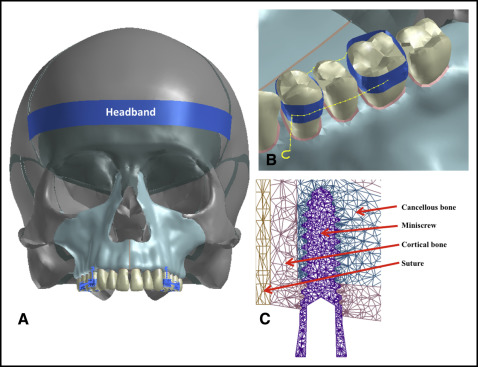
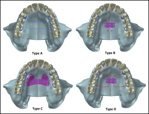
In type B, the miniscrews were placed 3 mm lateral to the midpalatal suture and connected to the expander via 0.9-mm stainless steel wires. In type C, the miniscrews were placed at the palatal slope, 8 mm beneath the alveolar ridge: 2 between the canines and first premolars, and 2 between the second premolars and first molars. The miniscrews were connected to the expander through an acrylic resin cover reinforced with 0.9 mm stainless steel wire. This wire shared some nodes with the miniscrews, and no relative motion was allowed between them.
The first premolars and first molars were banded (bands were meshed using shell elements connected to teeth using tied interface) and connected with 0.9-mm stainless steel wire (modeled using beam elements) at both the buccal and lingual sides. A protraction hook was attached to the band of the first premolar with the distal end 2 mm apical to the alveolar crest between the canines and first premolars. Bands were connected to the contralateral sides using an expander in type D (or stainless steel transpalatal archwires in type A).
The expanders were activated transversely for 0.25 mm at the level of the expansion screw in the y direction and unfixed in the z and x directions. A protraction force of 500 g was engaged at the hooks of the appliances. To minimize anticlockwise rotation, a 30° downward vector of the maxillary occlusal plane was applied. The displacement and von Mises stress distribution were assessed at the maxilla and the maxillary dentition. The geometric nonlinear theory was used for model analysis with PAM-MEDYSA software (version 2011; ESI Group) for solving and Visual-Viewer for postprocessing (version 7.0; ESI Group). The load step size was 0.1 (each step was 0.025 mm), displacement convergence tolerance was 0.0001, and force convergence tolerance was 0.01.
Results
Tooth displacement is shown in Table II and Figures 4 through 7 . In type A, FM only, the application of protraction forces showed anterior displacement of the maxillary dentition. The posterior teeth exhibited downward displacement of 0.02 mm, and the central incisor showed a minimal upward displacement of 0.006 mm.
| Type A | Type B | Type C | Type D | ||||||||||||||||||
|---|---|---|---|---|---|---|---|---|---|---|---|---|---|---|---|---|---|---|---|---|---|
| After protraction | After expansion | After protraction | After expansion | After protraction | After expansion | After protraction | |||||||||||||||
| x | y | z | x | y | z | x | y | z | x | y | z | x | y | z | x | y | z | x | y | z | |
| Central incisor incisal edge | 0.033 | −0.001 | 0.006 | −0.039 | 0.080 | −0.046 | −0.007 | 0.079 | −0.041 | −0.009 | 0.016 | −0.011 | 0.024 | 0.015 | −0.005 | 0.015 | 0.0002 | 0.020 | 0.046 | −0.001 | 0.027 |
| Central incisor apex | 0.022 | 0.000 | 0.001 | −0.040 | 0.037 | −0.050 | −0.018 | 0.037 | −0.051 | −0.008 | 0.006 | −0.011 | 0.014 | 0.006 | −0.011 | 0.008 | 0.002 | 0.017 | 0.030 | 0.002 | 0.019 |
| First premolar lingual cusp | 0.043 | 0.003 | −0.022 | −0.015 | 0.082 | 0.004 | 0.027 | 0.085 | −0.019 | −0.003 | 0.016 | 0.001 | 0.040 | 0.019 | −0.021 | 0.029 | 0.050 | −0.033 | 0.065 | 0.037 | −0.040 |
| First premolar buccal cusp | 0.043 | 0.003 | −0.021 | −0.009 | 0.079 | 0.008 | 0.033 | 0.083 | −0.014 | −0.002 | 0.016 | 0.002 | 0.041 | 0.019 | −0.019 | 0.021 | 0.052 | −0.022 | 0.060 | 0.039 | −0.032 |
| First premolar buccal root | 0.033 | 0.002 | −0.023 | −0.009 | 0.067 | 0.007 | 0.024 | 0.069 | −0.017 | −0.002 | 0.013 | 0.002 | 0.032 | 0.014 | −0.021 | 0.017 | 0.002 | −0.026 | 0.047 | 0.004 | −0.037 |
| First molar DL cusp | 0.042 | 0.001 | −0.024 | −0.010 | 0.099 | 0.011 | 0.030 | 0.101 | −0.014 | −0.002 | 0.020 | 0.003 | 0.039 | 0.021 | −0.021 | 0.020 | 0.023 | −0.022 | 0.058 | 0.019 | −0.036 |
| First molar MB cusp | 0.042 | 0.001 | −0.023 | −0.003 | 0.097 | 0.011 | 0.037 | 0.098 | −0.013 | −0.001 | 0.019 | 0.003 | 0.041 | 0.020 | −0.020 | 0.012 | 0.025 | −0.016 | 0.053 | 0.020 | −0.031 |
| First molar palatal root | 0.034 | 0.001 | −0.025 | −0.007 | 0.100 | 0.011 | 0.026 | 0.101 | −0.014 | −0.001 | 0.020 | 0.003 | 0.033 | 0.020 | −0.022 | 0.022 | 0.003 | −0.024 | 0.050 | 0.004 | −0.038 |
| First molar MB root | 0.034 | 0.001 | −0.024 | −0.001 | 0.097 | 0.011 | 0.032 | 0.098 | −0.013 | 0.000 | 0.019 | 0.003 | 0.034 | 0.020 | −0.021 | 0.015 | 0.007 | −0.019 | 0.047 | 0.007 | −0.033 |
Type B, the paramedian miniscrew expander, demonstrated posterior and outward displacement of the whole dentition along with downward displacement anteriorly and upward posteriorly after the application of the expansion forces. Then, after protraction, the posterior teeth showed anterior displacement, and the central incisors had a minimal backward displacement. The upward displacement of the posterior region changed to a downward one.
Type C, the palatal-slope miniscrew expander, showed a similar displacement tendency as type B but at smaller magnitudes.
For type D, the tooth-borne expander, expansion forces resulted in anterior and outward displacement of the maxillary dentition with downward displacement of posterior teeth but upward displacement of the incisors. Then, after protraction, there was an anterior displacement of the whole dentition (0.05-0.07 mm). The amount of expansion decreased posteriorly and become almost zero at the central incisor. There was an increase in the vertical displacement.
The amount of alveolar bone displacement was similar to the corresponding dental landmarks except for the vertical direction of type D in which the posterior alveolar bone showed a small upward displacement, whereas the teeth showed downward displacement ( Table III ).
| Type A | Type B | Type C | Type D | ||||||||||||||||||
|---|---|---|---|---|---|---|---|---|---|---|---|---|---|---|---|---|---|---|---|---|---|
| After protraction | After expansion | After protraction | After expansion | After protraction | After expansion | After protraction | |||||||||||||||
| x | y | z | x | y | z | x | y | z | x | y | z | x | y | z | x | y | z | x | y | z | |
| Central incisor lin alv crest | 0.028 | −0.001 | 0.002 | −0.038 | 0.071 | −0.049 | −0.010 | 0.071 | −0.048 | −0.008 | 0.013 | −0.011 | 0.020 | 0.013 | −0.010 | 0.012 | 0.001 | 0.017 | 0.039 | 0.000 | 0.020 |
| Bone at central incisor apex | 0.022 | 0.000 | 0.001 | −0.039 | 0.035 | −0.052 | −0.018 | 0.035 | −0.053 | −0.008 | 0.005 | −0.012 | 0.014 | 0.005 | −0.011 | 0.008 | 0.002 | 0.017 | 0.029 | 0.002 | 0.019 |
| Central incisor lab alv crest | 0.027 | 0.000 | 0.005 | −0.039 | 0.047 | −0.048 | −0.013 | 0.047 | −0.045 | −0.008 | 0.008 | −0.011 | 0.018 | 0.008 | −0.007 | 0.011 | 0.001 | 0.019 | 0.036 | 0.001 | 0.025 |
| First premolar midway palatal | 0.027 | −0.001 | −0.004 | −0.020 | 0.084 | −0.017 | 0.006 | 0.084 | −0.022 | −0.004 | 0.016 | −0.004 | 0.023 | 0.016 | −0.008 | 0.011 | 0.001 | 0.013 | 0.037 | 0.000 | 0.010 |
| First premolar lin alv crest | 0.028 | −0.001 | −0.003 | −0.018 | 0.089 | −0.013 | 0.010 | 0.089 | −0.017 | −0.004 | 0.017 | −0.003 | 0.025 | 0.017 | −0.006 | 0.012 | 0.001 | 0.014 | 0.039 | 0.000 | 0.012 |
| Bone at first premolar apex | 0.022 | 0.000 | −0.003 | −0.007 | 0.048 | 0.005 | 0.015 | 0.048 | 0.001 | −0.001 | 0.008 | 0.002 | 0.021 | 0.008 | −0.002 | 0.007 | 0.002 | 0.013 | 0.029 | 0.002 | 0.011 |
| First premolar buc alv crest | 0.028 | −0.001 | −0.001 | −0.005 | 0.076 | 0.011 | 0.023 | 0.076 | 0.009 | −0.001 | 0.015 | 0.003 | 0.027 | 0.015 | 0.002 | 0.011 | 0.001 | 0.014 | 0.037 | 0.000 | 0.014 |
| First molar midway palatal | 0.027 | −0.001 | −0.010 | −0.017 | 0.106 | −0.008 | 0.010 | 0.105 | −0.019 | −0.003 | 0.021 | −0.001 | 0.025 | 0.021 | −0.011 | 0.011 | 0.001 | 0.008 | 0.036 | 0.000 | 0.000 |
| First molar lin alv crest | 0.029 | −0.001 | −0.010 | −0.012 | 0.117 | 0.001 | 0.016 | 0.117 | −0.009 | −0.002 | 0.024 | 0.000 | 0.027 | 0.023 | −0.009 | 0.012 | 0.000 | 0.009 | 0.040 | −0.001 | 0.001 |
| Bone at first molar palatal apex | 0.024 | 0.000 | −0.010 | −0.009 | 0.087 | 0.004 | 0.015 | 0.087 | −0.007 | −0.002 | 0.016 | 0.001 | 0.023 | 0.016 | −0.009 | 0.009 | 0.001 | 0.009 | 0.032 | 0.000 | 0.001 |
| Bone at first molar palatal apex | 0.025 | 0.000 | −0.009 | −0.001 | 0.084 | 0.017 | 0.023 | 0.084 | 0.008 | 0.000 | 0.016 | 0.004 | 0.025 | 0.016 | −0.004 | 0.009 | 0.001 | 0.009 | 0.032 | 0.000 | 0.002 |
| First molar buc alv crest | 0.029 | −0.001 | −0.009 | 0.003 | 0.109 | 0.028 | 0.032 | 0.109 | 0.018 | 0.001 | 0.022 | 0.007 | 0.030 | 0.022 | −0.002 | 0.012 | 0.001 | 0.009 | 0.039 | −0.001 | 0.002 |
Stay updated, free dental videos. Join our Telegram channel
VIDEdental - Online dental courses


