Introduction
Our objective was to test the value of minisensors for recording unrestrained head position with 6 degrees of freedom during 3-dimensional stereophotogrammetry.
Methods
Four 3-dimensional pictures (3dMD, Atlanta, Ga) were taken of 20 volunteers as follows: (1) in unrestrained head position, (2) a repeat of picture 1, (3) in unrestrained head position wearing a headset with 3-dimensional live tracking sensors (3-D Guidance trackSTAR; Ascension Technology, Burlington, Vt), and (4) a repeat of picture 3. The sensors were used to track the x, y, and z coordinates (pitch, roll, and yaw) of the head in space. The patients were seated in front of a mirror and asked to stand and take a walk between each acquisition. Eight landmarks were identified in each 3-dimensional picture (nasion, tip of nose, subnasale, right and left lip commissures, midpoints of upper and lower lip vermilions, soft-tissue B-point). The distances between correspondent landmarks were measured between pictures 1 and 2 and 3 and 4 with software. The Student t test was used to test differences between unrestrained head position with and without sensors.
Results
Interlandmark distances for pictures 1 and 2 (head position without the sensors) and pictures 3 and 4 (head position with sensors) were consistent for all landmarks, indicating that roll, pitch, and yaw of the head are controlled independently of the sensors. However, interlandmark distances were on average 17.34 ± 0.32 mm between pictures 1 and 2. Between pictures 3 and 4, the distances averaged 6.17 ± 0.15 mm. All interlandmark distances were significantly different between the 2 methods ( P <0.001).
Conclusions
The use of 3-dimensional live-tracking sensors aids the reproducibility of patient head positioning during repeated or follow-up acquisitions of 3-dimensional stereophotogrammetry. Even with sensors, differences in spatial head position between acquisitions still require additional registration procedures.
The relatively recent transition in orthodontics from 2-dimensional (2D) to 3-dimensional (3D) imaging and from analog to digital technology has created renewed impetus for finding a versatile method for establishing accurate and reliable head positioning during the acquisition of serial records. During the analog era, orthodontists used cephalostats to orient radiographic films for diagnosis and tracking longitudinal changes from either growth or treatment. In the digital era, head orientation for the virtual patient presents a new challenge. When viewing a digital image on a computer screen, there is no external reference to establish the natural orientation of the head and teeth. Cone-beam computerized tomography (CBCT) and 3D photographic imaging offer new possibilities for more comprehensive diagnosis and treatment planning in clinical orthodontics because they give far more information than the previous 2D records. However, additional tools are required to achieve accuracy and reliability in the capture of these images, and proper orientation is important for future superimposition of the images to assess changes. Matching records taken at 2 times requires a more complex computer registration than was heretofore necessary. This research project addressed the issue of recording head position when it is unrestrained as it is during image capture for 3D photography or CBCT.
Head orientation has been a subject of great interest for clinical and research orthodontists for more than a century. In 1882, the General Congress of the German Anthropology Society agreed on a standard skull orientation proposed by Von Ihering. His suggestion was that a line, named the Frankfort horizontal, extending from the upper ridge of the external auditory meatus to the most inferior portion of the orbit should be parallel to the floor. This strictly anatomic method of skull orientation could only be used for dry skulls, plaster facial moulages, and dental casts. When Broadbent and Hofrath proposed radiographic cephalometry in 1931, for the first time it was possible to study living heads; because of their proposed stereotactic head-holding device, the cephalometer, it was possible to study facial growth longitudinally. The positioning of the head in the cephalostat initially chosen for this purpose was the orientation proposed by Von Ihering—the Frankfort horizontal. However, in 1956, Downs, using photographs, demonstrated variations in the Frankfort horizontal plane when subjects were in natural head posture. This prompted Moorrees and Kean, in 1958, to introduce in the orthodontic literature a physiologic position, natural head position. Natural head position is determined largely by the visual axis and can be obtained by having the subject stand and look at the horizon. Alternatively, a mirror can be placed in front of the subject and ask him or her to look at the eyes in the mirror. Natural head position was originally proposed by Broca to replace the anatomic method with the Frankfort horizontal plane. Vig et al observed changes in natural head position as a result of respiratory obstruction, and discussed that posture and respiration had implications in the control of growth and the establishment of dentofacial morphology.
Several authors tested the reliability of natural head position in 2 dimensions using lateral cephalometric radiographs. Others used photographs in addition to cephalograms to help in testing the reproducibility of natural head position. In all of these studies, the evaluations and comparisons of natural head position were with 2D images. The reproducibility of natural head position was evaluated for the capture of 3D images by Xia et al, who achieved natural head position for stereolithographic skull models of patients with dentofacial deformities with 2 methods. The first consisted of a laser scan capturing the facial soft-tissues’ surface and matching it with a rendered composite skull model. The second technique used a gyroscope attached to a face-bow that provided the pitch, yaw, and roll angulations of the patient’s head, which was used to reorient the skull on the computer. The reproducibility of head position in 3 dimensions was also studied by Soncul and Bamber. Using a facial laser scan, a headrest, and a spirit level, they showed high accuracy in reproducing head orientation; however, the Frankfort plane was used rather than natural head position.
The objective of this study was to test the effectiveness of minisensors in achieving repeatable head positioning. Because currently available imaging equipment is not designed for a standing patient, it was necessary to have our test subjects sit, rather than stand, although a mirror was used in front of them to simulate natural head position. The ultimate goal of this project was to redesign the imaging equipment, if necessary, and use the 3D sensors to record natural head position.
Material and methods
Twenty volunteers (13 men, 7 women; mean age, 32.80 ± 8.7 years; range, 20.3-55.6 years) were selected for this study. The exclusion criteria were (1) dentofacial deformities, (2) facial hair, (3) orthodontic appliances, (4) clinical diagnosis of asymmetry, (5) pacemaker, and (6) lip incompetence. The protocol was approved by the Biomedical Institutional Review Board of the University of North Carolina, and informed consent was obtained from all subjects.
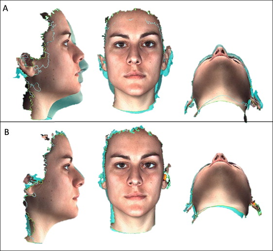
Three-dimensional surface images of each patient were acquired with the 3dMD face system (3dMD, Atlanta, Ga) on the same day ( Fig 1 ) in 4 situations: (1) the patient in unrestrained head position, (2) repeated picture with the patient in unrestrained head position, (3) the patient in unrestrained head position wearing a headset with tracking sensors, and (4) repeated picture of the patient in unrestrained head position wearing a headset with tracking sensors ( Fig 2 ).
The seat for the 3D photograph acquisition was a chair with (1) the ability to adjust the seat’s vertical height to accommodate subjects of varying heights and (2) a back support to help the subjects simulate their standing posture. Because the subnasal and submental regions are prone to data loss and artefacts, proper head posture ensured that these regions were visible to the imaging sensors of the camera. If the subject’s head tilted forward even a few degrees, these facial regions were often obliterated, and it was necessary to remind the subject to sit up straight. In addition to obvious signs of facial tension (eg, furrowed brow) or emotional expressions, the operators paid attention to the subject’s mouth and eyes. The subject’s eyes were open and the mouth was closed during capture, with the lips gently pressed together to prevent variations in lip posture.
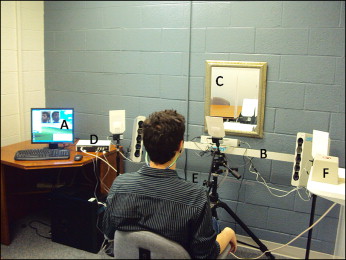
For all situations, the patients were asked to sit in front of a mirror, look forward, and try to position their facial midline with the “true vertical” tape (positioned at the center of the mirror). An assistant helped position each subject by moving the chair into the camera viewing area ( Fig 3 ). The assistant did not ask the subject to move the head or neck at any time during the initial pictures with or without sensors. Between each acquisition, the volunteer was asked to stand, walk around, and move the chair to minimize bias in the reproducibility of the repeated pictures. For the without-sensor initial and repeated photographs, the patients were simply asked to find their most comfortable positions.
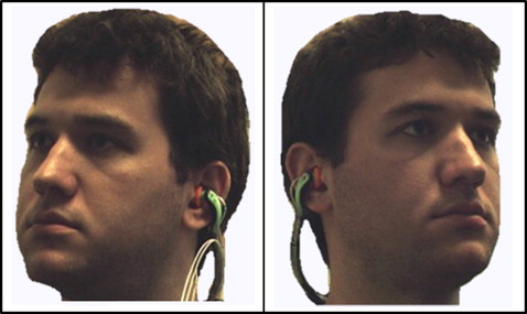
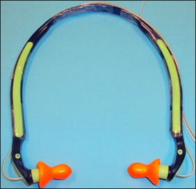
For the third and fourth acquisitions, 3-D Guidance trackSTAR (Ascension Technology, Burlington, Vt), a 3D real-time tracking system consisting of miniaturized 6 degrees of freedom sensors, was used. This is an electromagnetic tracking system where a midrange transmitter generates pulsed direct-current magnetic fields for high-accuracy tracking of the position of the attached minisensors. This system is designed to also be used in surgical navigation systems that follow anatomic bodies, instruments, or devices in the operative scenario. The system provides tracking of actual object positions in relation to the skull base and assistance for manipulating the object into the desired configuration. In this study, 3 minisensors of the 3D guidance system were attached to a commercially available band-type hearing protector, ordinarily used for reducing the effects of shop or industrial noise. A hole was made in each auricular part of the protector to fit 2 sensors (each was 1 mm in outer diameter by 10 mm in length). The third sensor was attached to the middle of the band ( Fig 4 ). All 3 sensors were plugged into a main unit, which communicated to the computer via a universal serial bus port. Software (Cubes; Ascension Technology Corporation, Burlington, Vt) tracked the real-time coordinates of the 3 attached sensors. The sensors were fitted in the patients’ ears, and the band was pushed to the neck. Removing sweatshirts with hoods and tucking in collars and other clothing articles around the neckline facilitated adequate capture of the neck, mandible, and ear. Each of the 3 sensors recorded 6 degrees of freedom in head position: the x, y, and z (inferior-superior, posteroanterior, and latero-lateral) distances from the center of the transmitter, and the x, y, and z rotational coordinates (roll, pitch, and yaw data) for each patient at the moment of acquisition of the third and fourth pictures. For the photographs captured with sensors, an assistant helped with chair movement and head tilt to reach the same x, y, and z positions (in millimeters) and the same pitch, yaw, and roll angulations (in degrees) from the initial (photograph 3) to the repeated (photograph 4). It was theorized that the closer the values were for x, y, and z between photographs 3 and 4, the better the reproducibility should be.
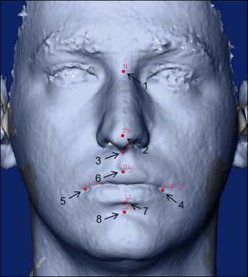
After acquisition, each image was loaded into the software 3dMD Patient (3dMD) and exported as a stereolithography (STL) binary file. All STL files were converted to .IV extension by using the STL to SGI Inventor 2.0 (IV) Utility Beta (developed by Reuben Reyes, hitechmex@austin.rr.com ). The software cranio-maxilofacial (CMF) application (developed at the M. E. Müller Institute for Surgical Technology and Biomechanics, University of Bern, Bern, Switzerland, with funding of the computer-aided and image-guided medical interventions (Co-Me) network, http://co-me.ch ) was used to locate anatomic landmarks in the 3D photos and to measure landmark distances between acquisitions. Landmarks were placed by the same operator (L.K.P.) in 8 sites: (1) nasion, (2) tip of nose, (3) subnasale, (4) right lip commissure, (5) left lip commissure, (6) midpoint of upper lip vermilion, (7) midpoint of lower lip vermilion, (8) soft tissue B-point ( Fig 5 ). For 10 subjects, the landmark identification was repeated 3 times to assess intraobserver reliability. Distances between the same landmarks were measured between images 1 and 2 and between images 3 and 4.