The midpalatal area has no critical anatomic structures and has thick cortical bone. These conditions are favorable for miniscrew implantation. Also, there is no concern that damaging a dental root in this area would cause failure of the miniscrew. Although these advantages can decrease the failure rate of miniscrews, midpalatal miniscrews have not been as popular as interdental miniscrews. Because the midpalatal area is far from the teeth, the utility of midpalatal miniscrews has been considered to be limited. This article describes a new method for controlling the maxillary dentition with 2 midpalatal miniscrews.
There is little controversy regarding whether temporary anchorage devices or skeletal anchorage devices have widened and expanded the horizons of orthodontic tooth movement limitations. The possibilities of an orthodontic regimen as a tool to solve dental and skeletal problems have expanded, and orthognathic surgery can even be minimized in certain cases.
Miniscrews are the most popular and simplest type of skeletal anchorage device with a simple procedure for implantation and removal. They have a screw part that is implanted into the bone and an upper part that is projected into the oral space that can accommodate a variety of orthodontic devices, including elastics and springs. The most preferred site for miniscrew implantation is the interdental alveolar bone between the second premolar and the first molar because miniscrews are commonly used as anchorage devices to retract the anterior teeth. In addition, this site is favored because of its ample interradicular space for miniscrew placement. However, many studies have reported that miniscrews implanted in the interdental area can fail for a variety of reasons, including root proximity to the miniscrews. Root contact of miniscrews is considered a main reason for their failure when placed in the interdental area.
Although many methods have been developed to prevent miniscrews from coming in contact with dental roots, and to decrease the failure rate, these procedures are either tedious or require specially designed equipment. In addition, for patients with congenitally narrow interradicular spaces, touching the roots while implanting the miniscrews is sometimes unavoidable, and additional procedures are needed.
To prevent root contact of miniscrews and decrease failure rates, nondental bearing areas, such as the retromolar area of the mandible and the midpalatal area of the maxilla, have been reported to be good sites for miniscrew implantation. These areas also have thick cortical bone that can reduce the failure rates of miniscrews compared with miniscrews placed in interradicular areas. However, the increased success rate has come at the cost of biomechanical convenience. Other mediating devices are required because these nondental bearing sites are far from the teeth that the clinician aims to move.
Several methodologies for miniscrews implanted in the midpalatal area have been proposed, but more biomechanical considerations and methodologies are needed to fully use midpalatal miniscrews to control the maxillary dentition. This article introduces a new method for controlling the maxillary dentition with 2 midpalatal miniscrews.
Material and methods
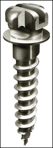
Two miniscrews (DualTop JD, Jeil, Seoul, Korea) with a 0.215 × 0.250-in rectangular slot were used for each patient ( Fig 1 ). Among the various sizes, 6-mm length and 1.60-mm diameter screws were used preferably. The rectangular slot can accommodate orthodontic archwires up to 0.215 × 0.250 in. The implanted miniscrews are connected to a 0.215 × 0.250-in rectangular stainless steel wire bent to fit the slots. Steel ligature ties are needed to secure the wire to the miniscrews.
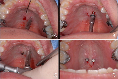
Two miniscrews were implanted in the midpalatal area. The implant site was approximately 1 to 2 mm from the midpalatal suture transversely, and the anteroposterior position was determined according to the treatment objectives. However, the position of the miniscrews is not of great importance because the force is not applied directly to them but to the miniscrew-connecting wire. Even if the miniscrews are implanted in an unintended place, this can be overcome by adjusting the miniscrew-connecting wire. After a mucosal disinfection treatment and the application of local anesthestic, a mucosal incision was made with a number 15 surgical blade. The bone surface was exposed with a small periosteal elevator, and a perforation of the cortical bone was made with a drill bur mounted on a low-speed hand piece ( Fig 2 , A ). The miniscrew was implanted by using a low-speed contra-angle hand piece ( Fig 2 , B ). Cortical perforation and miniscrew implantation were performed under saline-solution irrigation. After most of the screw part implantation had been achieved, the miniscrews were turned for a half to 1 more turn to parallelize the slots ( Fig 2 , C and D ).
After implanting the miniscrews, a rubber impression was taken by using a light-body injection-type vinyl polysiloxane impression rubber material and a heavy-body putty vinyl polysiloxane impression rubber material. First, light-body rubber was injected over the miniscrews and surrounding mucosa with care not to capture air bubbles ( Fig 3 , A ). After initial polymerization of the light-body rubber, heavy-body putty was applied over the light-body putty covering more of the palatal mucosal surface ( Fig 3 , B ). After polymerization of the rubber material, they were removed from the oral cavity and examined carefully for any air bubbles captured in the miniscrew impressed area ( Fig 3 , C ). Two additional miniscrews were fitted to the miniscrew impressed area of the impression body and secured with cyanide adhesive ( Fig 3 , D ). These miniscrews were used as analogs for the midpalatal miniscrews. The miniscrew-impression body complex was then placed in the bottom of a hollow open cylinder, and mixed stone was poured on the complex ( Fig 3 , E and F ). After the stone had hardened, the stone and impression body were separated, leaving the miniscrew analogs incorporated in the stone ( Fig 3 , G ) This stone model and miniscrew analog complex is a precise replica of the palate and the miniscrews.
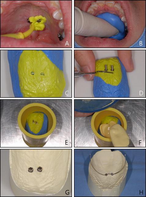
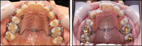
A 0.215 × 0.250-in rectangular stainless steel wire was bent to fit the 2 minscrew slots passively ( Fig 3 , H ). This wire connects the 2 miniscrews tightly and enables them to withstand the moments created from an orthodontic force that might loosen the miniscrews. This is why 2 miniscrews are needed. The wire also works as a support where orthodontic forces are applied or extended and come in direct contact with the dentition to exert the orthodontic forces. By adjusting the position of the wire, the force application points can be optimized in various situations of tooth movement without needing to relocate the screw position. Clinical applications are described as follows.
For the intraoral delivery of the miniscrew connecting wire, the laboratory fabricated connecting wire is usually well fit to the intraoral real miniscrews. Mostly only minor adjustments are needed to passively place the wire. However, if major adjustments are required, it might be better to repeat the laboratory procedure with a new rubber impression than to adjust the wire directly in the intraoral space. After the connecting wire was passively fit, its terminal ends of were generally bent to obtain a suitable position and shape to admit or exert orthodontic forces. The connecting wire was then secured to the miniscrews by tight wire ligation.
To provide absolute anchorage for retraction of the 6 anterior teeth ( Fig 4 ), a miniscrew-connecting wire can be fabricated to extend to the appropriate height according to the treatment objective (if bodily tooth movement is required, then height can be one third to two thirds of the root height) with the hooks bent distally. The 6 anterior teeth were splinted to a large tooth with a figure-8 tie ligature wire, and lingual buttons were bonded to the palatal side of the canines. Coil spring or elastomers were connected to the hooks and lingual buttons to provide a retraction force to the anterior teeth.