Computed tomography (CT) and cone-beam CT (CBCT) technology allows three-dimensional evaluation of each patient’s individual anatomy. This article highlights the presurgical planning phase of dental implant procedures that benefit from lower dose CBCT technology so that educated treatment decisions can be accurately determined. Clinicians should gain an understanding of how each view can be individually significant, with unique levels of detail helping to provide a comprehensive overview of the patient’s anatomic presentation. This article outlines the benefits of using CBCT technology for dental implant applications for increased accuracy and avoidance of potential surgical and restorative complications.
Computed tomography (CT) and cone beam CT (CBCT) technology allows for an unprecedented three-dimensional (3D) evaluation of each patient’s individual anatomy. The advent of this technology has evolved into an indispensable diagnostic tool that can be used for a variety of different clinical applications that include, but are not limited to: dental implant receptor site evaluation; alveolar bone defect and bone augmentation procedures; impacted teeth; orthodontics; endodontics; temporomandibular (TM) joint diagnostics; sinus augmentation procedures; and orthognathic surgical interventions. The presurgical planning phase of these applications that benefit from CBCT technology starts with the accumulation of data for which educated treatment decisions can be accurately determined. Adapting to the ALARA (as low as reasonably achievable) principle, the radiation dosages from CBCT have been minimized through the process of collimation, and reduction in scan time, yet maintaining a high degree of diagnostic accuracy. The benefits versus the risks should be considered when determining the need for a scan. The purpose of this article is to show the benefits of using CBCT technology for dental implant applications.
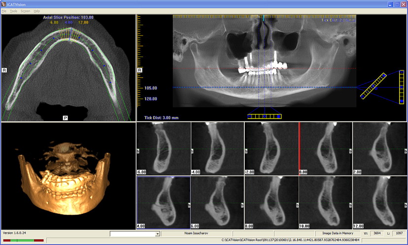
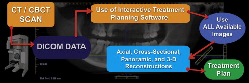
A myriad of CBCT scanning machines are available in the United States and around the world that claim to deliver high-quality diagnostic images with machine-specific variations on how this can be achieved. In addition, each machine is driven by proprietary software to obtain and visualize the 3D dataset. Once a scan has been taken, the interpretation process begins regardless of which software is used. Each manufacturer allows clinicians to visualize and interact with the data for the purposes of diagnosis and treatment planning. There are 4 important 3D views; (1) axial, (2) cross-sectional, (3) panoramic, and (4) 3D reconstructions ( Fig. 1 ) (i-CAT Vision, Imaging Sciences Inc, Hatfield, PA). Each of these views is individually important, providing unique levels of detail. When assimilated in total as a result of the interactive nature of the CBCT native software, these views provide the ultimate overview of the patient’s anatomic presentation. The data can also be exported into DICOM (digital imaging and communications in medicine) files that can be visualized through third-party interactive treatment planning software applications that have innovative tools to enhance the diagnosis and treatment planning process. The author has long advocated the concept that “It’s not the scan, it’s the plan,” meaning that the clinician must evaluate and interpret the data provided by the CBCT machine to establish accurate treatment options using innovative state-of-the-art digital tools. Once the scan is taken, it can be viewed on the computer workstation using the native software (ie, i-CAT Vision), or the DICOM data can be exported into an interactive treatment planning software such as SimPlant (Materialise Dental, Glen Burnie, MD, USA), NobelGuide (Nobel Biocare, Göteborg, Sweden), Invivo5 (Anatomage, San Jose, CA, USA), (VIP Software, BioHorizons Inc, Birmingham, AL, USA), Straumann coDiagnostiX (Straumann USA, Andover, MA, USA), Blue Sky Plan (BlueSkyBio Grayslake, IL, USA), where all available images can be processed and manipulated interactively to create an excellent diagnostic environment ( Fig. 2 ).
Benefits versus risks
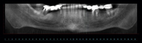
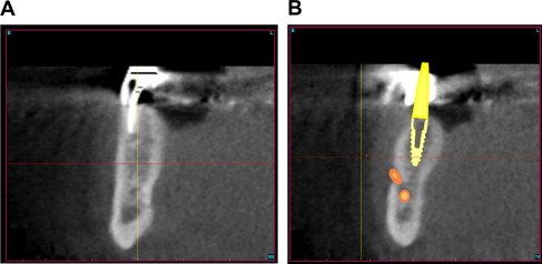
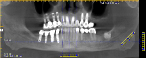
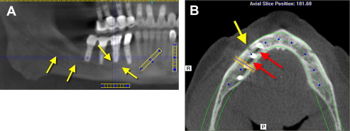
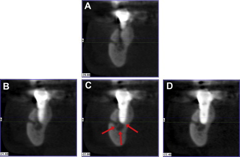
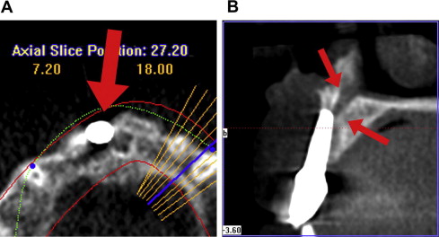
During the evolution of CT and CBCT, clinicians worldwide discovered what the author has labeled the “reality of anatomy” or the patient’s individual anatomic 3D presentation. When a preoperative scan is not performed, potential complications can occur, and issues are then discovered with a postoperative scan. A postsurgical, postreconstruction CBCT scan (i-CAT) was performed after the mandibular right paresthesia did not resolve. The panoramic reconstruction revealed implants placed in 3 quadrants, the right, left, and anterior maxilla, and right mandible ( Fig. 3 ). The image can be enlarged to focus on the area of interest such as the path of the inferior nerve and the proximity of the previously placed implants ( Fig. 4 A). To gain a great appreciation of the local anatomy, the axial slice created perpendicular to the panoramic slice reveals the break in the facial cortical bone (see Fig. 4 B, yellow arrow), which indicates the mental foramen. The radiolucent areas between the implants could represent the inferior alveolar nerve, or it could also be a phenomenon called beam hardening, which turns the pixels in proximity to dense objects radiolucent (see Fig. 4 B, red arrows). To differentiate, it is necessary to review the cross-sectional slices. Cross-sectional slices revealed that the implant closest to the mental nerve penetrated into the inferior alveolar nerve canal ( Fig. 5 ). If a CBCT scan had been taken before the implant placement either a shorter implant could have been used, or a different receptor site might have been used.
Another paresthesia case resulted from a perforation into the incisal canal. An axial view revealed an implant placed in the area of the right maxillary central incisor ( Fig. 6 A). The implant appeared to perforate through the facial cortical plate (see Fig. 6 A, large red arrow). The cross-sectional slices clearly illustrated the apical extent of the implant that invaded the incisal canal space causing long-lasting postoperative complications (see Fig. 6 A, arrows).
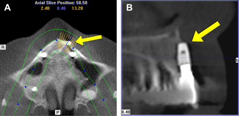
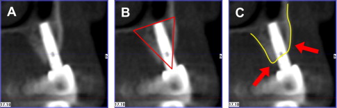
A third example of a malpositioned implant can be visualized in the axial slice of a left maxillary lateral incisor ( Fig. 7 A, yellow arrow). The implant significantly perforates through the facial cortical bone. The cross-sectional view further illustrates that 50% of the implant is not located within the alveolar housing (see Fig. 7 B). The yellow arrow reveals the apical portion of the implant is located within the soft-tissue vestibule. When a preoperative scan is used, implants can be positioned where they are surrounded with a good volume of bone. A cross-sectional slice of an implant in function for 10 years can be visualized in Fig. 8 A. The implant was positioned within the zone that the author has defined as the “triangle of bone,” providing the most volume of surrounding bone (see Fig. 8 B). The maxillary topography reveals a typical pattern where the bone is higher on the palate or lingual, and lower on the buccal or facial (see Fig. 8 C). This bone pattern and implant placement are defined as transitional placement. Therefore there are known risks in placing implants without 3D diagnosis and surgical guidance with CT-derived templates. Potential serious complications can be avoided when 3D imaging tools are used, as is shown later.
Case presentation: failing long-span mandibular bridge
Treating failed long-span bridges presents unique challenges for the clinician and the patient. When anchor abutment teeth fail, and it is recommended that the bridge be removed, often it can no longer be supported by natural teeth. The treatment option to replace the missing dentition consists of a removable-type prosthesis, or an implant retained restoration. Most patients do not want to be without teeth for an extended amount of time and desire the option that most closely replaces their missing teeth: a fixed prosthesis. Many patients are now aware of treatment options that allow for removal of the failing bridge and anchor teeth followed by the immediate placement of dental implants to maintain an immediate transitional restoration. However, in order to present this treatment option to the patient, proper diagnosis and treatment planning are essential for a complete understanding of the available bone, soft tissue, opposing occlusion, vertical dimension, and surrounding vital structures. Current two-dimensional panoramic and periapical radiographs can no longer be considered the most accurate diagnostic imaging modalities available.
To properly assess the patient’s anatomy, the author recommends 3D assessment using CBCT technology, which empowers the clinician with new tools to make educated decisions regarding the plan of treatment.
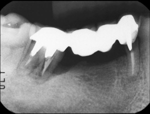
A 61-year-old male patient presented with pain and mobility in an existing posterior right mandibular long-span fixed bridge. A routine diagnostic workup was completed, including periapical radiographs and study casts. The patient had a history of bruxism, which may have been contributory to the root fractures and mobility of the bridge. Radiographic loss of bone was evident around the mandibular second molar tooth, the terminal abutment for the fixed bridge, which showed a significant angular defect on the mesial ( Fig. 9 ). The first bicuspid had previously been treated with root canal therapy, and appeared to be fractured from the stress of the restoration and/or recurrent decay along the margins. To determine the potential treatment alternatives a CBCT scan was ordered to allow complete inspection of the 3D bony topography, and the relationship of adjacent vital structures. Two-dimensional imaging modalities could not provide an adequate interpretation of the patient anatomy, raising the risk of treatment and potential injury to vital structures.

Case presentation: failing long-span mandibular bridge
Treating failed long-span bridges presents unique challenges for the clinician and the patient. When anchor abutment teeth fail, and it is recommended that the bridge be removed, often it can no longer be supported by natural teeth. The treatment option to replace the missing dentition consists of a removable-type prosthesis, or an implant retained restoration. Most patients do not want to be without teeth for an extended amount of time and desire the option that most closely replaces their missing teeth: a fixed prosthesis. Many patients are now aware of treatment options that allow for removal of the failing bridge and anchor teeth followed by the immediate placement of dental implants to maintain an immediate transitional restoration. However, in order to present this treatment option to the patient, proper diagnosis and treatment planning are essential for a complete understanding of the available bone, soft tissue, opposing occlusion, vertical dimension, and surrounding vital structures. Current two-dimensional panoramic and periapical radiographs can no longer be considered the most accurate diagnostic imaging modalities available.
To properly assess the patient’s anatomy, the author recommends 3D assessment using CBCT technology, which empowers the clinician with new tools to make educated decisions regarding the plan of treatment.
A 61-year-old male patient presented with pain and mobility in an existing posterior right mandibular long-span fixed bridge. A routine diagnostic workup was completed, including periapical radiographs and study casts. The patient had a history of bruxism, which may have been contributory to the root fractures and mobility of the bridge. Radiographic loss of bone was evident around the mandibular second molar tooth, the terminal abutment for the fixed bridge, which showed a significant angular defect on the mesial ( Fig. 9 ). The first bicuspid had previously been treated with root canal therapy, and appeared to be fractured from the stress of the restoration and/or recurrent decay along the margins. To determine the potential treatment alternatives a CBCT scan was ordered to allow complete inspection of the 3D bony topography, and the relationship of adjacent vital structures. Two-dimensional imaging modalities could not provide an adequate interpretation of the patient anatomy, raising the risk of treatment and potential injury to vital structures.
3D planning
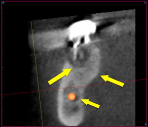
The panoramic image reconstructed from the CBCT dataset differs substantially from a conventional panoramic radiograph. This nondistorted image can be viewed interactively using the incorporated viewing software to assess the broader aspects of the arches ( Fig. 10 ). The cross-sectional image is excellent for defining a slice of the mandible where the height and width of the bone can be accurately evaluated. Within an individual slice, the spatial location of the tooth and root can be appreciated ( Fig. 11 A). The facial, lingual cortical, and intermedullary bone can be visualized based on their radiopacity or gray-scale density values. Nuances within the anatomic presentation can be assessed with greater accuracy than with any other imaging modality. Simulated implants can be placed in a position to effectively support the desired restoration, even with close proximity to the mental foramen (see Fig. 11 B). The cross-sectional slice of the posterior molar reveals the significant bone defect surrounding the apical roots ( Fig. 12 ). A significant lingual concavity was noted with the pattern of cortical bone visualized below the root apex (see Fig. 12 , yellow arrows). The inferior alveolar nerve can be carefully traced through the mandible to determine proximity to the tooth roots and potential implant receptor sites (see Fig. 12 , orange). Although there was good-quality bone above the location of the nerve, there was insufficient bone to adequately fixate an implant after immediate extraction. It was therefore elected to remove the molar tooth and fill the defect with grafting material in anticipation of placing an implant after the new bone had matured.