Introduction
The proper angle of microimplant insertion is important for cortical anchorage, patient safety, and biomechanical control. However, the actual impact of different insertion angulations on stability is unknown.
Methods
To perform 3-dimensional finite element analysis, finite element models of a maxilla and a mandible with types D3 and D2 bone quality, and of microimplants with a diameter of 1.3 mm and lengths of 8 and 7 mm were generated. The microimplants were inserted at 30°, 45°, 60°, and 90° to the bone surface. A simulated horizontal orthodontic force of 200 g was applied to the center of the microimplant head, and stress distribution and its magnitude were analyzed with a 3-dimensional finite element analysis program.
Results
The maximum von Mises stresses in the microimplant and the cortical bone decreased as the insertion angle increased. Analysis of the stress distribution in the cortical and cancellous bones showed that the stress was absorbed mostly in the cortical bone, and little was transmitted to the cancellous bone. The maximum von Mises stress was higher in type D3 bone quality than type D2 bone quality.
Conclusions
Placement of microimplants at a 90° angulation in the bone reduces the stress concentration, thereby increasing the likelihood of implant stabilization. Perpendicular insertion offers more stability to orthodontic loading.
Skeletal anchorage provided by temporary anchorage devices has attracted great attention in recent years because of its versatility, minimal surgical invasiveness, and low cost.
The proper angle of insertion is important for cortical anchorage, patient safety, and biomechanical control. The use of a proper insertion angle reduces the risk of damaging the dental roots of adjacent teeth and also provides increased surface contact area between the microimplant and the bone. But the actual impact of different insertion angulations on microimplant stability is unknown.
It is virtually impossible to measure stress accurately around microimplants in vivo. Also, it is difficult to achieve an analytical solution for problems involving complicated geometries such as the maxilla and the mandible, which are exposed to various kinds of loads.
Finite element analysis provides an approximate solution for the response of the 3-dimensional (3D) structures to the applied external loads under certain boundary conditions. It appears to be suitable for simulating complex mechanical stress situations in the maxillofacial region.
The objectives of this study were to generate finite element models of the maxilla, the mandible, and the microimplant, to simulate orthodontic loading for en-masse retraction, and to evaluate the stress patterns in the bone and the microimplant immediately after loading with different insertion angulations of the microimplant.
Material and methods
Three-dimensional finite element models were created for the following components after scanning them with computed tomography with a slice thickness of 1.5 mm: (1) the maxilla and the mandible in dentitions with the first premolars extracted, (2) the periodontal ligament, (3) the alveolar bone, (4) a standard preadjusted edgewise bracket (slot size, 0.018 × 0.025 in), (5) a stainless steel archwire (0.016 × 0.022 in), (6) a stainless steel power arm, (7) a nickel-titanium closed-coil spring, and (8) AbsoAnchor microimplants (SH1312-08 and SH1312-07; Dentos, Taegu, Korea).
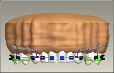
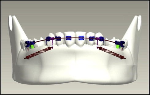
The images were obtained in a DICOM (digital imaging and communication in medicine) data format. These images were then reconstructed to a 3D model by using Pro/ENGINEER software (Parametric Technology, Needham, Mass). All these components were individually modeled and then assembled to create 3D finite element models of the maxilla and the mandible depicting en-masse retraction of 6 anterior teeth ( Figs 1 and 2 ). The entire assembly was then exported for analysis with ANSYS Workbench (version 11.0; ANSYS, Canonsburg, Pa) through a bidirectional understandable translated system called initial graphics exchange specification.
A 3D finite element model of each tooth was constructed according to the method of Wheeler, and all teeth were aligned with reference to the facial axis point of Andrews. The labiolingual and buccolingual inclinations of the teeth were simulated based on the studies of Kim et al. The maxillary and mandibular dentitions were established according to the normal arch shapes of Roth (Tru-arch forms, medium size; Ormco, Orange, Calif).
The 3D finite element models of the periodontal ligament were constructed to fit outside the root. Based on the studies of Kronfeld and Coolidge, the thickness of the periodontal ligament was considered to be 0.25 mm evenly, although periodontal ligament thickness is different according to age, position, and individual variations. The 3D finite element models of the alveolar bone were fabricated to fit the teeth and the periodontal ligament.
Three-dimensional finite element models of 0.018 × 0.025-in standard preadjusted edgewise brackets (3M Unitek, Monrovia, Calif) were made and attached to the crown so that the facial axis point was at the center of the bracket slot.
Three-dimensional finite element models of the archwires (0.016 × 0.022 in) were designed according to Roth’s normal arch shapes and cinched at the distal part of the first molar tube.
Three-dimensional finite element models of 4 power arms were generated and attached to the archwire distally to the lateral incisor bilaterally and perpendicularly to the archwire.
Three-dimensional finite element models of a nickel-titanium closed-coil spring were designed and stretched between the microimplant and the hook between the lateral incisor and the canine to deliver 200 g of force.
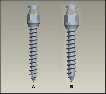
Three-dimensional finite element models of 2 types of AbsoAnchor microimplants were constructed ( Fig 3 ). The microimplants had similar diameters and varied only in length: (1) (small head) SH1312-08, self-drilling, tapered type for the maxilla and (2) (small head) SH1312-07, self-drilling, tapered type for the mandible.
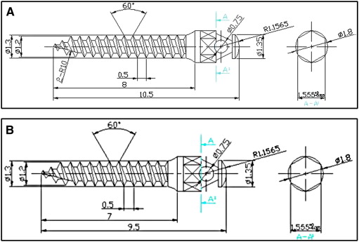
Since these implants had small dimensions and to ensure greater accuracy in constructing these finite element models, the dimensions and measurements of the implants ( Table I ) were obtained from the AbsoAnchor company ( Fig 4 ).
| Implant parameters | Maxilla SH1312-08 |
Mandible SH1312-07 |
|---|---|---|
| External diameter | 1.3 mm | 1.3 mm |
| Head size | 2.5 mm | 2.5 mm |
| Implant body length | 8 mm | 7 mm |
| Overall length | 10.5 mm | 9.5 mm |
| Pitch | 0.5 mm | 0.5 mm |
The microimplants were placed 5 to 8 mm from the alveolar crest in the interradicular space between the first molar and the second premolar in the maxilla, and 11 mm from the alveolar crest in the interradicular space between the first molar and the second premolar in the mandible based on studies by Poggio et al. The microimplants were inserted at 30°, 45°, 60°, and 90° to the bone surface.
The finite element models were considered to have linear elasticity and isometric properties of the same quality. Young’s modulus and Poisson’s ratio for the teeth, periodontal ligament, bracket, and wire were calculated according to the methods of Vollmer et al and Reimann et al.
Young’s modulus and Poisson’s ratio for the trabecular bone varied depending on the bone quality available where the microimplant was placed ( Table II ). Type 3 (D3) bone quality was present in the posterior maxilla with a thin layer (1 mm) of cortical bone surrounding a core of dense trabecular bone of favorable strength. Type 2 (D2) bone quality was present in the posterior mandible with a thick layer (2 mm) of compact bone surrounding a core of dense trabecular bone. Hence, the implant length also varied depending on the thickness of the cortical bone.
| Materials | Young’s modulus (MPa) | Poisson’s ratio |
|---|---|---|
| Tooth | 20,000 | 0.30 |
| Periodontal ligament | 0.05 | 0.30 |
| Alveolar bone | 2,000 | 0.30 |
| Bracket/archwire/powerarm | 200,000 | 0.30 |
| Closed-coil spring | 110,000 | 0.35 |
| Microimplant | 110,000 | 0.35 |
| Cortical bone | 13,700 | 0.30 |
| Cancellous bone (D3) | 1,600 | 0.30 |
| Cancellous bone (D2) | 5,500 | 0.30 |
Three-dimensional quadrangular and hexagonal elements were used for the tooth and standard preadjusted edgewise bracket models. The periodontal membrane was constructed with thin shell elements and the archwires with 3D beam elements. The number of nodes and elements are shown in Table III .
| Bone model | Insertion angulation | Number of nodes | Number of elements |
|---|---|---|---|
| Maxilla | 30° | 13,242 | 6976 |
| Maxilla | 45° | 13,454 | 7173 |
| Maxilla | 60° | 14,200 | 7597 |
| Maxilla | 90° | 13,986 | 7541 |
| Mandible | 30° | 10,471 | 5342 |
| Mandible | 45° | 11,616 | 6066 |
| Mandible | 60° | 11,570 | 6141 |
| Mandible | 90° | 11,917 | 6367 |
To simplify the model and reduce the time for analysis, a bone block was modeled for the study. The bone block, measuring about 8 × 14 × 10 mm (height, width, and depth), represented the sections of the maxilla and the mandible in the interradicular spaces between the first molar and the second premolar where the microimplant was inserted at 4 different angulations. The section of bone contained the outer cortical bone and the inner trabecular bone. Since the cortical bone thickness in the insertion areas of the maxilla and the mandible is between 1 and 2 mm, respectively, 4 models for the maxilla and the mandible were developed for varying the insertion angulations, because the implant lengths were 8 mm in the maxilla and 7 mm in the mandible. Hence, 8 finite element models with 2 implant lengths, 2 cancellous bone types, and 4 insertion angulations were generated for the study ( Table IV ).
| Model | Bone model | Cortical bone thickness | Implant length | Insertion angulation |
|---|---|---|---|---|
| 1 | Maxilla | 1 mm | 8 mm | 30° |
| 2 | Maxilla | 1 mm | 8 mm | 45° |
| 3 | Maxilla | 1 mm | 8 mm | 60° |
| 4 | Maxilla | 1 mm | 8 mm | 90° |
| 5 | Mandible | 2 mm | 7 mm | 30° |
| 6 | Mandible | 2 mm | 7 mm | 45° |
| 7 | Mandible | 2 mm | 7 mm | 60° |
| 8 | Mandible | 2 mm | 7 mm | 90° |
The retraction force was applied bilaterally to the center of the microimplants through the closed-coil springs from the microimplant anchorage to each power arm. A simulated retraction force of 200 g was loaded mesiodistally to the center of the microimplants, and stress distribution and its magnitude were analyzed by ANSYS Workbench, a 3D finite element analysis program. An assessment of the stress on the bone elements was performed by using von Mises equivalent stress.
Results
A color scale with 9 stress values was used to evaluate quantitatively the stress distribution in the bone and the microimplant ( Figs 5 , C, and 6 , C ). The scale for stress runs from 0 MPa ( blue ) to the highest stress values ( red ). Red indicates areas with the highest stress, and blue indicates areas with the lowest stress.
The stress distributions on the implant-bone-interface with 30° insertion angulation as an example is shown in Figures 5 and 6 . Stress was highly concentrated in the head and neck of the implant, the contact point between the implant thread and cortical bone, and the cortical bone surrounding the implant. The cortical bone was subjected to higher stress levels than the cancellous bone irrespective of the insertion angle of the microimplant. The cortical bones around the threads of the implant were the most stressed areas. Little stress was transmitted to the cancellous bone. The maximum von Mises stress values induced in the microimplant, cortical bone, and cancellous bone at the 4 insertion angulations in the maxilla and the mandible are shown in Table V , and the comparison of the maximum von Mises stress values are depicted in Figures 7 and 8 .


