Introduction
Registering a 3-dimensional (3D) facial surface scan to a cone-beam computed tomography (CBCT) scan has various advantages. One major advantage is to compensate for the inaccuracy of the CBCT surface data. However, when registering CBCT and 3D facial scans, changes in facial expression, spatial soft-tissue changes, and differences in the patient’s positioning can decrease the accuracy of the registration. In this study, we introduce a new 3D facial scanner that is combined with a CBCT apparatus. Our goal was to evaluate the registration accuracy of CBCT and 3D facial scans, which were taken with the shortest possible time between them.
Methods
The experiment was performed with 4 subjects. Each patient was instructed to hold as still as possible while the CBCT scan was taken, followed immediately by the 3D facial surface scan. The images were automatically registered with software. The accuracy was measured by determining the degree of agreement between the soft-tissue surfaces of the CBCT and the 3D facial images.
Results
The average surface discrepancy between the CBCT facial surface and 3D facial surface was 0.60 mm (SD, 0.12 mm). Registration accuracy was also visually verified by toggling between the images of the CBCT and 3D facial surface scans while rotating the registered images.
Conclusions
Registration of consecutively taken CBCT and 3D facial images resulted in reliable accuracy.
Accurate diagnosis is the key to treatment planning and a successful treatment outcome. Many clinicians evaluate facial contours, especially the profile, when setting goals for treatment. From the perspectives of function, stability, and esthetics, the orthodontist must plan treatment within the patient’s limits of soft-tissue adaptation and contours. Holdaway emphasized that the best possible soft-tissue profile should be established first, followed by tooth movement that will best develop the patient’s ideal profile. Park and Burstone challenged the idea that optimal occlusion and strict adherence to hard-tissue cephalometric standards lead to good facial form. They concluded that using a cephalometric standard based on hard tissues alone would not produce a given profile type, and that achieving good facial esthetics requires consideration of the overlying soft-tissues in orthodontic treatment planning.
It is essential to analyze accurate imaging data that represent the “anatomic truth” of the patient’s real anatomy. Diagnostic imaging has been a part of orthodontic patient records for decades. Traditionally these images are 2-dimensional (2D) cephalometric images and tracings, panoramic images, and 2D photographs. Three-dimensional (3D) data were confined to study models. One standard diagnostic tool in orthognathic surgery and preoperative orthodontic treatment is the 2D facial photograph. These diagnostic elements have serious limitations in a thorough evaluation of the 3D structures of a patient’s face. Over the past few years, cone-beam computed tomography (CBCT) has been used to aid in diagnosis and treatment planning. However, soft-tissue images taken from CBCT data are not very accurate and do not capture the true color and texture of the skin.
Recently, studies have been conducted to merge the CBCT images to the 3D facial surface scans. Schendel and Lane described the advantages of anatomically registering 3D facial surface images to CBCT data. They proposed that surface images can correct CBCT surface artifacts caused by several situations. Patient movement is more likely when the patient is upright rather than supine (ie, swallowing, breathing, head movement, and so on). The time interval to take the CBCT scans can vary among machines from 5 to 70 seconds, and a longer interval allows more movement. CBCT device stabilization aids (chin rest, forehead restraint) can distort the surface anatomy recorded in the CBCT image. Surface images also can supplement any missing anatomic data (nose, chin, and so on) when taking a CBCT scan of an upright patient. Finally, a surface scan provides a more accurate representation of the draping soft tissues that reflect the patient’s natural head position.
In a typical 2D cephalograph, hard-tissue and soft-tissue images are represented in 1 image. Therefore, there is no margin of error in the correlation between them. However, errors can occur when registering a CBCT image with a 3D facial photo or surface scan. Any errors in the integration of the 3D soft tissues and skull models could increase the cumulative errors of the prediction planning method and could transfer to errors in orthodontic or surgery planning. Reducing errors during registration of the CBCT and 3D surface scans is beneficial for a correct diagnosis. In this preliminary study, we aimed to introduce a new 3D facial scanner combined with a CBCT apparatus and to evaluate the registration accuracy of CBCT and 3D facial surface scans that were taken with the least possible time between scans.
Material and methods
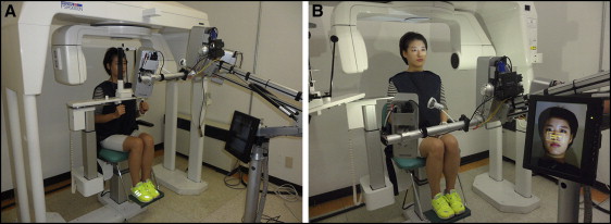
CBCT and 3D facial surface scans are usually taken in different locations and at different times before being merged. Ayoub et al reported that registration errors were within ±1.5 mm when CBCT and 3D facial surface scans were taken separately. These errors were attributed to minor changes in facial expression, spatial soft-tissue changes, and differences in the patient’s positioning during capture. In their study, facial scans were taken in the sitting position, and the CBCT scan was taken in the supine position. According to Naudi et al, the level of superimposition accuracy from the delayed captures was between 0.3 and 0.9 mm, whereas the superimposition accuracy for the simultaneously captured images was 0.4 mm or less. In our study, a 3D facial scan was taken immediately after a CBCT scan in the same room and with the patient in the same posture. These scans were used to evaluate registration accuracy. A 3D optic scanning system (3D Neo; Morpheus, Gyoung-gi, Korea) was used for the 3D facial surface scans ( Fig 1 ). This system uses white light from light-emitting diodes because it is safe to eyes. It acquires a 3D surface image by projecting structured patterns on the subject and analyzing the deformation of the patterns. When patterned light is projected on an object, the sensor acquires on-and-off light information. Scanning is sensitive to surface material properties such as strongly reflective or translucent objects compared with noncontact and passive methods. This scanning method was less restricted because of its compact size (height, 200 cm; depth, 80 cm; width, 90 cm) and the transmission of the data by Wi-Fi.
The Morpheus 3D software automatically registers the extracted skin surface of the CBCT image and the surface of the 3D facial scan to obtain optimal registration parameters based on the rigid transformation including the x-axis, y-axis, and z-axis translations and rotations. Therefore, skin surface registration corrects any translational and rotational mismatches. The first step of the registration is voxelization of the 3D facial image. A 3D mesh vertex of the 3D facial scan is projected into voxels in the CBCT data. Coordinate systems of 3D facial scan data and CBCT volume data should be matched. Agreement of the 2 coordinates is verified with a 1-voxel dilation operation. Then, the center of the CBCT image and the mesh coordinate of the 3D facial data are aligned and loaded. Next is skin segmentation. The surface of the skin was determined by extracting the air boundary because the skin is surrounded by air. The acquired images were first modified by a thresholding step, excluding all pixels with densities less than −1024 HU and more than −670 HU. Then, an extraction step was carried out to delineate the air edge. A chamfer distance map algorithm was used to accelerate a registration speed by referring to a precalculated distance value and by eliminating burdens of point-to-point correspondence identification. Chamfer distance transformation reduces the generation time of the distance map by an approximated distance transformation compared with a Euclidean distance transformation. Chamfer distance transformation can be generated by performing a sequence of local operations while scanning the image twice. During optimization, search range and step are dynamically changed to achieve finer alignments quickly and robustly.
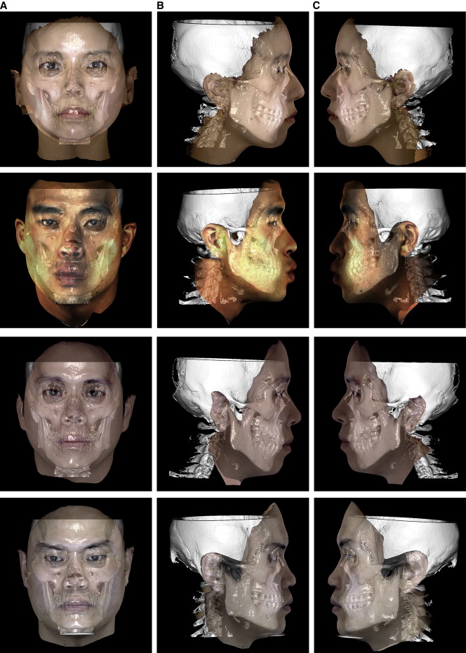
This experiment was performed with 4 subjects (1 woman, 3 men) to investigate the accuracy of the automatic registration between CBCT and 3D facial surface scans ( Figs 2 and 3 ). A computer (Core2 Quad Q8400 2.66GHz, 8.0 GB main memory; Intel, Fort Worth, Tex) with Windows 7 operating system (Microsoft, Redmond, Wash) was used. The 3D facial scanner was installed in the computed tomography room. Calibration was conducted to establish a topologic location between the camera and the projector. Immediately after the CBCT scan was taken (Alphad Vega; Asahi Roentgen, Kyoto, Japan), the 3D facial scan was taken (see Videos 1 and 2 , available at www.ajodo.org ). The scanning procedures were carried out according to the manufacturer’s instructions. The patients sat 60 to 70 cm in front of the camera. Patients with long hair were advised to wear a hairband to prevent interference of the scanning by hair. The scanning process was straightforward. Three pictures were taken (frontal, right oblique, and left oblique) using image-acquiring software (Facemaker; Morpheus).
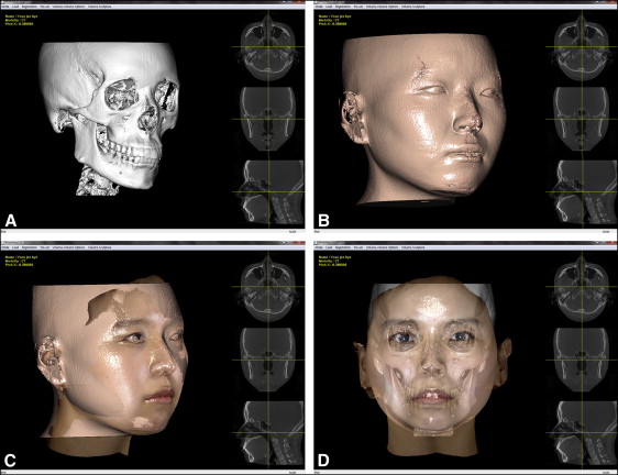
Once scanning of all 4 subjects was completed, the CBCT image was opened with the manufacturer’s software (Morpheus 3D). Only the hard tissue of the skull was visible at that moment ( Fig 2 , A ). The skin surface was extracted by a thresholding process ( Fig 2 , B ). At that point, the software was ready to automatically register the CBCT and the 3D facial surface images. Once the 3D facial image was opened, the 2 images were automatically registered without the need for fine adjustments ( Fig 2 , C and D ). After registration, the axis of the face was manually aligned. By using the button on the control panel, the y-axis and the z-axis of the face could be adjusted (laterally and anteroposteriorly tilted) to the natural head position.
After automatic registration, the distance measure in the Equation was used to determine the degree of resemblance of soft-tissue surfaces of the CBCT and 3D facial images. The average surface distance between the 2 surfaces (ASD) reaches the minimum when the soft-tissue boundary points of the CBCT and 3D facial images are accurately matched. DistanceMap CT (P) is the distance value of P in the 3D distance map of the CBCT image. Transform(P) is the rigid transformation of point P in the 3D facial image. P SurfaceScan (i) is the i th boundary point of the 3D facial image. N SurfaceScan is the total number of surface points in the 3D facial image. The average surface distance was calculated for all skin surfaces in each slice.
Stay updated, free dental videos. Join our Telegram channel
VIDEdental - Online dental courses


