5 Imaging and planning technologies
5.1 Endoscopy in mandibular condyle and midfacial trauma care
1 Introduction
Surgical management of craniomaxillofacial trauma has undergone significant evolution over the course of the last 100 years. Nevertheless, several facial areas have remained that could not be approached without obvious surgical stigmata, most notably the mandibular condyle, zygomatic arch, the orbit, and frontal sinus. Those fractures where the benefits of repair outweighed operative risks were treated using open reduction and internal fixation (ORIF). Others, when perceived posttraumatic deformity and dysfunction were less discernable were approached more conservatively, or simply not treated. The decision on how to manage these specific fractures was based on individual surgeon’s experience and patient preferences.
Endoscopy was initiated to the field of craniomaxillofacial surgery by Vasconez et al who performed the first endoscopic brow lift in 1994. This relatively delayed introduction was caused partly by the absence of naturally occurring cavities in the head and neck region. The nasal cavity and paranasal sinuses were too small to allow for the introduction of at least two of the early instruments necessary for the principle of triangulation and unrestricted manipulation. Additional detractors to the popularization of endoscopic craniomaxillofacial surgery were the absence of specialized instrumentation, initially lengthy operative times and significant equipment expenses. Relentlessly, through cadaver studies to first clinical applications, facial endoscopy pioneers introduced novel techniques of exposing and repairing facial injuries through strategically located minute incisions into mechanically dissected optical cavities, avoiding large scars and vital structures. Most notable are the works of Sakai et al [1996] on Le Fort I and III osteotomies, Kobayashi et al [1995] and Lee et al [1997] on zygomatic arch and mandibular condyle, Forrest [1999], Shumrick [2001], Strong et al [2003], Chen [2003], and Stanley [1989] on frontal sinus and orbit, and Troulis [2004] on mandibular osteotomies. Together with the development of specialized craniomaxillofacial endoscopic instrumentation, these were the pivotal steps in allowing a wider spread application of endoscopeassisted techniques to facial trauma care.
The endoscope is of great benefit to the facial trauma surgeon. It allows for a minimally invasive access to craniomaxillofacial injuries that could previously only be reached using wide open exposures and their associated risks, while still permitting anatomical fracture realignment and rigid fixation. The endoscope has two principal roles in facial trauma management. First, it decreases the morbidity of surgical access in injuries where ORIF is considered the current standard, for example the zygomatic arch. Second, it allows for anatomical repair of injuries that were previously mainly treated nonoperatively or not at all due to perceivably unacceptable operative risks, for example the mandibular condyle.
In this chapter, the rationale, specific indications, surgical techniques and complications of the endoscope-assisted techniques for the repair of mandibular condyle, zygomatic arch, orbital walls, and frontal sinus are presented. The discussion of future directions of craniomaxillofacial endoscopy will follow.
2 Indications
2.1 Mandibular condyle
2.1.1 Rationale
Temporomandibular joint (TMJ) anatomy is highly complex. The condylar head is elliptically shaped in the axial plane, measuring on average 20 mm in width and 10 mm in length. It articulates with the glenoid fossa, which is only slightly larger, measuring 23 mm in width and 15 mm in length. The anterior wall of the fossa is inclined at 30° to the sagittal plane and guides translatory motion. Its medial wall has a slope of 15° in the coronal plane and directs lateral excursive movements. Clearly, only minimal imprecisions can be tolerated at the finely tuned temporomandibular articulation. A malunited condyle alters these precise relationships resulting in significant aberrations in joint dynamics which have a marked potential to produce late internal derangement. Furthermore, the bilateral interdependence of the craniomandibular articulation imposes excessive biomechanical loads on the contralateral condyle, similarly predisposing it to early degenerative changes.
Condylar fractures account for 20–50% of mandibular injuries. For decades these fractures had been treated using mandibulomaxillary fixation (MMF) with seemingly good outcomes. However, careful inspection of the effects of MMF has shown that fracture reduction is rarely achieved and some malunion generally results following displaced fractures. Centric occlusion is thus forced through neuromuscular adaptation at the TMJ. The malunion is not inconsequential, leading to a decreased posterior ramal height due to interfragmentary overlap, abnormal orientation of the condylar head and alteration of TMJ biomechanics, with secondary esthetic and functional disturbances.
In bilateral condyle fractures, with shortened rami, the mandibular plane may rotate clockwise causing an unappealing loss of chin projection through the pogonion. In this position, an anterior open bite of several millimeters may exist. Only seldom and briefly, for instance during chewing, are maximal intercuspidation and chin position forcefully restored. Furthermore, in unilateral condyle fractures, ramus shortening decreases the ipsilateral radius of mandibular rotation resulting in a mechanically disadvantaged jaw deviation during motion.
Next, the anteroposteriorly flexed condylar posture, occurring due to the pull of the lateral pterygoid, and present in more than 80% of adult fractures, results in its premature contact with the anterior wall of the glenoid fossa. Interincisal opening is limited to only the initial 20–25 mm of hingetype motion. Further, 15–20 mm available through translation along the articular eminence is not fully achieved.
Mandibulomaxillary fixation is not tolerated by certain patient populations, such as those with dementia or psychiatric diagnoses. Inability to freely move the mandible can also be potentially dangerous in those suffering from a seizure disorder or substance abuse, as these patients are at an increased risk for aspiration. Even when tolerated, MMF is frequently uncomfortable and leads to weight loss and difficulties in maintaining proper oral hygiene. The prolonged period of MMF immobilization necessitates a lengthy postoperative regimen of muscular and occlusal rehabilitation to recover muscle function, and condylar range of motion. These issues are far from trivial as they can have negative consequences on patients’ general state of health.
Clearly, results of non-surgical treatment of adult condylar injuries with major displacement have not been encouraging. Recent long-term studies comparing ORIF versus MMF confirm the advantage of open techniques, despite the fact that they were used to treat more severe injuries. The reluctance to open repair of the mandibular condyle was also due to the real risk of facial nerve injury, introduction of visible scarring and technical challenge. The risk of permanent facial nerve palsy using transcutaneous surgery averages 1% and transient dysfunction occurs in 0–46% of cases. External incisions almost universally result in perceptible scarring, and in 4% of patients will leave an unsightly mark. As an effect, many surgeons continued to treat condylar injuries in adult patients using MMF.
The introduction of the endoscope to craniomaxillofacial surgery shifted the tides in the traditional doctrine on condylar trauma management. Endoscopic assistance allows the surgeon to achieve the preferable goal of anatomical fracture realignment using a path devoid of cutaneous incisions, which minimizes risk of injury to the facial nerve. The negative sequelae of condylar malunion, a frequent outcome of isolated MMF, can no longer be accepted as the fateful result of treatment.
2.1.2 Treatment indications
Walker [1994] suggested five goals for condylar fracture treatment: pain-free mouth opening with interincisal distance over 40 mm, good movement of the jaw in all excursions, preinjury occlusion of the teeth, stable TMJs, and good facial and jaw symmetry. Mandibulomaxillary fixation may achieve these objectives in some injuries. Fractures in prepubertal patients may not always require accurate reduction due to the immense potential for condylar rehabilitation through growth and restitutional remodeling. For fractures without significant loss of ramus height non-surgical treatment can be expected to produce favorable functional and esthetic results. The last group comprises stable injuries with minimal displacement and no dislocation.
The remaining fracture types benefit from consideration of anatomical reduction and rigid internal fixation to restore preinjury ramus height, upright posture of the condylar head and thus complex anatomical relationships of the temporomandibular articulation. A transcutaneous approach allows the surgeon to effect rigid anatomical repair but entails risk of injury to the facial nerve, whose course and branching pattern are difficult to exactly predict, and of visible scars. An open intraoral approach is intended to minimize these shortcomings but has not gained widespread acceptance because it provides less adequate visualization and makes hardware placement more difficult.
Endoscopic condylar repair thus may replace external techniques in the treatment of some of the fractures which are notorious for poor outcomes when treated with MMF. It is indicated for the treatment of adult condylar neck and subcondylar fractures with displacement or dislocation.
Today, precision, safety, and predictability of endoscopic treatment of condylar fractures also allows for the treatment of children older than 5 years, as in severely dislocated fractures. Remodeling during growth may not always be achieved in this age group and sequelae of the injuries can result in impaired function of the TMJ, associated with an abnormally shaped condylar head, reduced height of the mandibular ramus, and growth anomalies resulting in facial asymmetry. The endoscope may be useful in endoscopically assisted removal of foreign bodies near the condylar process as well as for endoscopic removal of condylar lesions.
3 Preoperative planning
3.1 Fracture anatomy
Careful patient selection is necessary to identify those fractures in which minimally invasive repair is feasible. This assessment includes the anatomical location of the fracture as well as the type and degree of displacement of the fragments, and whether sufficient bony space exists for the placement of fixation hardware.
3.2 Fracture location
The mandibular condyle can be subdivided into three surgically important anatomical zones: head, neck (below the capsule and above the sigmoid notch), and subcondyle. Fractures of the condylar head cannot be treated with endoscopically assisted procedures. Injuries of the neck region are amenable to endoscopic repair if the fracture is low enough to accept the application of at least two holes of a 2.0 mm miniplate into the proximal segment. Subcondylar fractures are most easily approached with the endoscope.
3.3 Fracture displacement
Fracture fragment displacement, defined as the relative position of the proximal to the distal mandible segments, must be considered before endoscopic repair. Fractures demonstrating lateral override, and those where the proximal fragment overlaps the lateral aspect of the ascending mandibular ramus, are easiest to treat. Hardware can be placed on the freely accessible lateral surface of the proximal segment and reduction obtained. Medial override injuries, those where the proximal fragment is overlapped laterally by the ramus, represent a greater challenge. Direct repair is not possible as the ramus obscures visual access to the lateral surface of the condylar fragment and greatly impairs manipulation due to physical obstruction. These injuries must be recognized on preoperative radiography and redisplaced under endoscopic guidance into lateral override. Fortunately, this subgroup accounts for less than 20% of adult condylar injuries. Nondisplaced, nondislocated fractures signify the presence of sufficiently stable periosteal support and do not require open treatment.
3.4 Fracture comminution
Visualization of a congruent fracture line, as well as smooth anterior and posterior borders of the condyle are the most important markers of anatomical reduction. Comminution involving the borders of the fracture significantly impedes, in proportion to its degree, the surgeon’s ability to accurately reposition the condylar segments to their preinjury status. A minor amount of comminution is not considered a contraindication. Severely comminuted fractures, however, should not be approached endoscopically. In addition to greatly increasing the difficulty of reduction, comminution does not allow for adequate fixation through the endoscopic approach.
4 Condyle—fossa relationship
Fractures without condylar head dislocation from the glenoid fossa are most favorable for endoscopic repair. When true fracture dislocation is present, repair is significantly more challenging.
4.1 Radiographic imaging
Fracture location, displacement, comminution and condylar head location must be assessed preoperatively to determine the feasibility of the endoscopic approach and to formulate an appropriate operative plan. Accurate radiographic imaging is thus an integral part of patient evaluation. Fine cut axial CT scans with 3-D reformatting provide the most precise illustration of the necessary variables and have been shown more sensitive than traditional panoramic tomography in detecting mandibular fractures. Reformatted images clearly show condylar fracture anatomy, but may underestimate the degree of comminution.
5 Operative technique
5.1 Equipment
Instruments required include a 4 mm diameter 30° angle scope, a 4 mm endoscopic brow lift sheath that maintains the optical cavity, and a video system composed of a camera, light source camera converter and monitor. Two video monitors placed on either side of the head make it easier for the surgeon and assistant to view the procedure. Standard mandible fracture repair instruments are used, in addition to the subcondylar ramus fixation set, which provides many specialized instruments and tools.
5.2 Repair sequence
Additional non-condylar mandibular fractures, if present, are addressed first using standard open reduction and rigid fixation techniques. This restores an intact mandibular arch that may then be used as a lever arm in manipulating fracture fragments to achieve accurate reduction.
5.3 Mandibulomaxillary fixation
The use of tight-wire MMF will often lock the displaced condyle in a malreduced position. Wire MMF must be removed before the commencement of condylar repair. Accurate reduction is judged by the alignment of the fracture fragments. Rubber band anterior MMF is routinely used as it facilitates repair by maintaining occlusion but permitting realignment of fracture fragments.
5.4 Exposure
Initial approach to this fracture is via an intraoral incision along the oblique line of the mandible. The endoscopic cavity is created by elevating the periosteum off the lateral surface of the ascending ramus under direct visualization. Transcutaneous incisions permit screw placement and are made directly over the palpated fracture line at the posterior border of the ramus. To minimize risk of injury to the facial nerve, gentle dissection using a blunt-tipped hemostat is performed through the parotid gland and masseter muscle. The retractor mounted endoscope is then inserted and further subperiosteal dissection of the proximal condylar fragment is carried out up to the joint capsule ( Fig 5.1-1 ). Importantly, the degree of overlap and angulation of the proximal condylar segment must be appreciated to avoid mistakenly confusing it with the ascending ramus.

5.5 Reduction
Medial override injuries are initially reduced into lateral override. This is achieved by placing a curved elevator medial to the proximal fragment, while strongly distracting the fracture so as to allow the proximal fragment to be displaced to the lateral surface of the ascending ramus ( Fig 5.1-2 ). For those injuries already in lateral override, interfragmentary realignment is achieved by distracting the distal segment through mechanical traction at the mandibular angle or placement of a posterior occlusal spacer. The proximal segment can be reduced by medially directed pressure using a trocar inserted through the percutaneous incision. Removal of traction or the posterior occlusal wedge will then permit the rubber band MMF to temporarily impact the fracture interfaces.

5.6 Fixation
A transcutaneous trocar serves to introduce the screws. A miniplate (2.0) is initially fixated along the posterior border of the proximal fragment, taking advantage of its thick cortical bone and flat surface. Using the plate as a handle, the condylar fragment is positioned into reduction. Screws are then placed in the distal fragment. A minimum of two screws are placed in each fracture segment to ensure solid fixation. A second plate is then fixated near the anterior portion of the fracture using a similar technique. If possible, placement of two miniplates is advocated to minimize the risk of stressinduced hardware failure ( Fig 5.1-1g ). Following hardware placement, rubber band MMF is released and the mandible moved in all excursions to ensure reproducible complete occlusion with the condyle seated in the fossa and adequate motion.
5.7 Postoperative regimen
All patients leave the operating room without MMF and are maintained on a puree diet for 6 weeks. Training elastics may help the patient adapt to function postoperatively. Representative case is shown in Fig 5.1-3 .

5.8 Results of endoscopic treatment of condylar fractures
Multi-year experiences with the transoral, endoscopically assisted treatment of displaced condylar fractures have been reported. In a series [Schön et al, 2005] of 62 fractures, a lateral dislocation of the fracture was observed in 58 patients. Medially displaced condylar heads (n = 17) and bilateral condylar fractures (n = 4) could also be treated with success, however. The use of angulated screwdrivers and drills provided good visibility of the fracture site and precise anatomical reduction in all patients. The average operation time was 1 hour 5 minutes.
In a prospective randomized double-blind study [Schmelzeisen et al, 2009] nonendoscopic ORIF using a transfacial approach was compared with patients with a transoral endoscopic procedure. The primary functional outcome measure was investigated using the asymmetric Helkimo dysfunction score at 8-12 weeks and 1 year after surgery. The nonendoscopic extraoral group (n = 34) and the endoscopically assisted open reduction group (n = 40) showed comparable functional results without any statistical significance. The endoscope-assisted treatment proved to be more time consuming. However, in the nonendoscopic group a greater number of facial nerve injuries were reported showing the reliability and the advantages of endoscope-assisted surgery for selected patients.
6 Contingencies and complications
In a number of cases, endoscopic repair will not be possible. This is most often due to inadequate proximal bone stock or excessive comminution. Careful preoperative CT image evaluation will minimize the number of such cases attempted. When used selectively, endoscope-assisted ORIF can be expected to reliably produce anatomical reduction and adequate stabilization in most cases. If the surgeon is unable to complete the endoscopic procedure, he/she should resort to the method of condylar repair which they would customarily use.
The largest published series [Müller et al, 2006] of endoscopic condylar fracture repair comprises 135 patients. Here the rate of malreduction in primarily endoscopically fixated fractures is 4%. Plate fracture is rare, accounting for less than 2% of cases. Less than 4% of patients do not regain interincisal opening greater than 35 mm. Permanent facial nerve injury has not been reported with this technique and temporary palsy occurs in less than 2% of cases.
In 13 patients [Schön et al, 2008] with endoscope-assisted transoral treatment of displaced bilateral condylar fractures a 6-month follow-up demonstrated a preinjury range of TMJ motion and the possibility of an intake of a normal diet. Limitations of lateral excursion were not noted. There was no clicking of the TMJ and no pain on movement. Twelve months after surgery a stable result regarding TMJ function was noted. In one patient, loosening of one screw was noted at the 12-month follow-up and plate removal was performed without any signs of fracture displacement or resorption.
7 Zygomatic arch
7.1 Rationale
The zygomatic arch forms one of the horizontal facial buttresses, supporting the frequently injured midface from the sturdy temporal bone posteriorly. The arch has a consistent shape. In the axial plane, it is curved in the posterior third of its course and straight in the anterior two thirds. On sagittal section, it is parallel to the Frankfurt horizontal.
Fractures of the zygomatic arch can be isolated or exist with other midfacial injuries. The injury pattern depends on the magnitude and direction of the trauma force vector as well as individual skeletal characteristics. Isolated arch fractures are of three types. First, direct lateral force displaces the arch medially. Second, an anterior force vector focused on the malar prominence will usually cause a posterior telescoping pattern of injury. Third, a posteriorly directed force can also result in an explosive burst with displacement of the arch fragments laterally. Recognition of the latter two injury patterns is important as a nonvisualized reduction attempt, as described by Gillies, will be unsuccessful and exacerbate fracture displacement.
The arch’s reliable shape, strategic location and coexistence of arch fractures with high-energy midfacial trauma allow numerous authors to use it as a key landmark support in midface fracture management [Gruss et al, 1990; Stanley, 1989]. The role of the arch in midfacial repair can be viewed as threefold. First, it can be used to guide precise fracture realignment to accurately restore midfacial projection; second, it can serve as an anchor point for the midface due to its sturdy skull base attachment; and third, its anatomical reduction is paramount to esthetic appearance in patients with increased facial width.
Despite the potential role of the zygomatic arch, its repair has been approached with caution, as access to it is challenging. Incisions should not be placed directly over the arch because of a possible facial nerve injury. To avoid facial nerve injuries the coronal approach was used to approach the arch indirectly from above and behind the facial nerve. Disadvantages of the coronal approach include scar alopecia, sensory disturbances posterior to the incision, traction injury to the frontal or zygomatic branches of the facial nerve, temporal hollowing, and excessive blood loss.
Endoscopy gives the surgeon the potential to utilize arch repair while minimizing the negative sequelae of traditional access. In addition, this technique offers other advantages including magnified direct visualization and a potential for rapid, cost-effective treatment.
7.2 Treatment indications
An endoscopic approach to the arch may be considered whenever precise arch repair is deemed an integral part of the treatment plan. Thus, when the zygomatic arch is thought to contribute to proper reduction and/or enhanced stability of other facial fractures or when the arch itself is considered an important esthetic and structural landmark, the surgeon may attempt endoscope-assisted ORIF. Specifically, endoscope-assisted ORIF of the zygomatic arch may be indicated in esthetically evident isolated arch fractures, zygomaticomaxillary complex (ZMC) fractures and Le Fort III level midface injuries.
In isolated arch fractures, repair is particularly important in individuals with prominent premorbid lateral facial contours.
Failure of realignment will lead to unsightly temporal flattening and asymmetry. In addition, miniplate fixation will prevent postoperative arch displacement, an issue which is not addressed by the Gillie’s or closed reduction approaches.
In posteriorly displaced ZMC fractures, arch reduction is a valuable tool for anatomical repositioning of the malar prominence and to restore normal facial width and projection. Also, medial repositioning of the ZMC restores adequate orbital volume. This is paramount in complex ZMC fractures where there may be extensive comminution of at least two of the three anterior buttresses. In these injuries, the arch also serves as an additional point of rigid fixation and zygomatic adjustment.
In Le Fort III level injuries, the principal benefit of rigid arch fixation is to stabilize and align the mobile midface to the skull base. This ensures secure midface dimensions and a stable occlusal relationship. The arch is particularly valuable when the other anterior buttresses are comminuted. The remaining role of the arch in Le Fort III fractures is to enhance accurate midfacial realignment.
Endoscope-assisted ORIF is unnecessary when a coronal flap is used for other fracture treatment, such as: nasoorbitoethmoid, posterior table of the frontal sinus or displaced skull fractures.
7.3 Preoperative planning
7.3.1 Radiographic imaging
Fine cut preoperative axial CT scans with coronal and sagittal reformatting is required to visualize arch fragmentation and displacement patterns. The presence of other midfacial injuries is ascertained to create a complete management plan. Aligning the zygoma in the lateral orbit with the greater sphenoid wing proves useful to establish the proper medial position of the zygomatic arch.
7.3.2 Repair sequencing
In nonisolated zygomatic arch injuries, the following sequence of fracture management is generally the most useful. For ZMC and Le Fort III fractures, endoscopic approaches to the arch can assist traditional open techniques.
8 Operative technique
8.1 Equipment
See section on: Mandibular condyle fractures/operative technique/equipment.
8.2 Exposure
A scalp extension of a preauricular incision is carried through the skin and the temporoparietal fascia to expose the deep temporal fascia. A periosteal elevator is then inserted and an optical cavity is created by dissecting superficial to the deep temporal fascia. This nonvisualized part of the dissection is performed only superior to an imaginary line extending from the helical crus to the superior orbital rim. This minimizes the risk of injury to the frontal branch of the facial nerve. Following dissection of the optical cavity, a retractor-mounted endoscope is inserted and directly visualized dissection in the same plane is performed down to the zygomatic arch ( Fig 5.1-4 ).

Maintenance of integrity of the deep temporal fascia helps to avoid temporal hollowing. Once the arch is reached, its periosteum is incised and the sites of fracture are exposed in the subperiosteal plane. Chen [2000] modified this approach by performing the dissection beneath the superficial layer of the deep temporal fascia. He incises the deep temporal fascia 1 cm above the zygomatic arch and then proceeds with the subperiosteal dissection to the upper margin of the zygomatic arch.
8.3 Reduction
Following exposure, arch fragments are reduced according to the fragmentation pattern to restore preinjury arch form.
8.4 Fixation
Selection of appropriate fixation hardware depends on the type of fracture. A short miniplate is used in isolated arch injuries whereas a long mini-adaptation plate is preferred in associated midfacial trauma. The long mini-adaptation plate extends onto the lateral orbital rim, restoring and rigidly stabilizing the midface. Following fixation of the plate to an arch segment, accurate reduction is confirmed and the plate is stabilized to other fracture segments using the endoscope ( Fig 5.1-4c ). Representative ZMC and Le Fort III fracture cases are shown in Fig 5.1-5 and Fig 5.1-6 , respectively.


8.5 Contingencies and complications
Review of the literature identified four eligible patient series (adequate follow-up, outcomes reported) comprising 78 patients. Incidence of temporary facial nerve palsy when dissection was performed beneath the superficial temporal fascia was 3 (5.6%) of 53. Chen [2000] describes no incidences of nerve palsy with his modified approach. He credits this to a greater level of protection from mechanical retraction afforded by a thicker layer of tissue. There have been no cases of permanent palsy. There is lesser risk of temporal hollowing when deep temporal fascia is not violated, thus preserving vascular supply to the fat pad.
If the endoscopic procedure cannot be completed, the surgeon should resort to a coronal or hemicoronal exposure to accomplish arch repair. In our experience this has been infrequent.
9 Orbital floor
9.1 Rationale
Orbital floor fractures may occur in isolation, when trauma applied directly to the globe or inferior orbital rim is transmitted to the floor, or as a necessary component of ZMC fractures. Size of the floor defect and presence of entrapped periorbital tissues determine treatment strategy. Floor fractures greater than 2 cm2 or 50% of total floor area significantly increase the risk of enophthalmos or hypoophthalmos development through orbital volume augmentation. Entrapped periorbital tissues may cause extraocular muscle imbalance, impeding binocular vision.
Currently, the diagnosis and precise characterization of orbital fractures can be accurately performed using noninvasive fine-cut coronal CT scanning. In cases where adequate preoperative imaging is unavailable or inaccurate, surgical exploration may be considered.
Traditional approaches to the orbital floor involve the use of a transfacial incision, either at the subciliary, transconjunctival, subtarsal or infraorbital level. Several undesirable sequelae are associated with such approaches, including visible scarring, scleral show and ectropion (1-42%). The transconjunctival approach presents significantly lesser morbidity but is however not devoid of complications. For example, ectropion (up to 7%), inferior oblique muscle injury, and entropion have been noted.
The endoscope offers the potential to avoid lower lid incisions in orbital floor fractures. The adjacent maxillary sinus offers a natural optical cavity with great exposure of the entire orbital floor. It may be accessed via an anterior maxillary wall antrostomy or transnasally.
9.2 Treatment indications
Currently, the endoscope is most useful as a diagnostic tool in cases where accurate CT imaging is unavailable or when the information is no longer accurate, for example after reduction of a ZMC fracture. Furthermore, it helps determine which cases require surgical repair.
Whenever floor repair is judged important, endoscopic approach may be considered and used if no contraindications exist. Endoscope-assisted repair of the orbital floor has been performed with success by numerous authors. It does, however, require significant endoscopic experience, specialized equipment and carries a potentially disastrous risk of ocular and optic nerve injury. Injuries which can most easily be repaired with the endoscope include trapdoor and medial orbital floor blowout fractures. Trapdoor fractures are frequently stable after reduction of orbital contents and can be left without fixation. Medial blowout injuries can be treated using a small alloplastic implant. Injuries lateral to the infraorbital nerve (ION), or those involving the medial orbital wall, require more extensive dissection and implant fixation. These are probably best approached through the lower lid.
For some fractures, which need treatment via open approaches, the endoscope may still serve as an adjunct to reducing entrapped periorbital tissue and identifying the posterior floor ledge for implant alignment.
9.3 Operative technique
9.3.1 Equipment
General endoscopic equipment required has been previously described. In addition, a smooth elevator and a 55° forked elevator are useful for mucosal dissection and implant manipulation. Standard orbital fracture instruments are also used.
9.3.2 Exposure
The maxillary sinus is used as the optical cavity in orbital floor injuries. It is entered most commonly through a transoral osteotomy of the anterior maxillary wall using a small osteotome or a piezoelectric device. This antrostomy should be approximately 1 x 2 cm large and situated 1-2 mm below the ION. Be cautious to avoid injuries to the ION or dental roots. Old blood is suctioned from the sinus and the endoscope is inserted and important structures (ION, maxillary sinus ostium) as well as fracture anatomy are visualized ( Fig 5.1-7 ).

Alternatively, the sinus may be entered intranasally using a small antrostomy under the uncinate process of the inferior turbinate. The uncinate process may be subluxed medially and removed. The “pulse test” may be used to diagnose clinically significant orbital floor defects. With the endoscope inside the antrum, digital pressure is applied to the globe. Only those fractures that allow intraorbital content herniation with this maneuver require repair.
9.4 Reduction and fixation
Trapdoor injuries are repaired using reduction only. A smooth elevator is used to expose 5 mm of bone at the lateral periphery of the defect. Avoid excessive medial dissection to preserve periosteal integrity. Traction is then placed on the bone flap to allow reduction of orbital contents. The bone flap is then released into position and fracture stability checked. Excessive comminution at the lateral fracture edge will require treatment similarly to medial blowout injuries.
Medial blowout fractures necessitate implant insertion. First, a smooth elevator is used to dissect 5 mm of maxillary sinus mucosa around the circumference of the defect. Similarly, 5 mm of periosteum is dissected circumferentially on the orbital side. All loose bone fragments are removed to permit proper stable ledge identification and prevent their inadvertent displacement into the orbit. This step is essential in minimizing surgical risks. Subsequently, an alloplastic implant is tailored to the defect pattern and inserted onto the orbital face of the fracture. Implant fixation is not required.
Lateral blowout fractures not involving the greater wing of the sphenoid may be repaired similarly to the medial blowout injuries. However, the extent of dissection is significantly greater and extreme care should be taken to prevent injury to the ION during dissection and implant placement. Specialized instrumentation is required for securing the implant. A representative patient example is shown in Fig 5.1-8 .

“The pulse test” is performed after implant insertion to ensure fracture stability. Routine forced duction test confirms no extraocular muscle entrapment.
9.5 Contingencies and complications
Osteoplastic antrostomy does not leave any contour deformities. Intraorbital misadventures are exceedingly rare but potentially disastrous, including orbital hemorrhage, optic nerve and ocular globe injury and extraocular muscle damage. Risk of nerve and globe injuries can be significantly decreased by ensuring the removal of all intraorbital fracture fragments before implant placement. Avoid excessive posteromedial dissection. In the eight published endoscopic floor fracture repair series, comprising 204 patients, there are no cases of either injury [Strong, 2004; Persons et al, 2002; Saunders et al, 1997; Ikeda et al, 1999; Hinohira et al, 2005; Nishiike et al, 2005; Otori et al, 2003; Chen et al, 2001]. The inferior rectus may be theoretically damaged during intraorbital manipulation; however, this had not been reported. Diplopia was improved in all patients with about 20% having some residual diplopia. Prevalence of long-term nerve disturbances is unknown.
In the endonasal technique, during middle meatal antrostomy, if enlargement of the ostium advances too far anteriorly, the nasolacrimal duct may be injured. There have been no complications with alloplastic implants used for endoscopic floor repair. In difficult cases, endoscopic exposure may be converted to open approaches.
10 Medial orbital wall
10.1 Indications and rationale
Medial orbital wall injuries are frequent. Theoretically their consequences on globe position may in fact be greater than that of orbital floor fractures, as the greater part of the medial wall lies behind the mid-axis of the ocular globe. The sequelae are similar to floor injuries and include extraocular muscle entrapment with secondary horizontal diplopia and enophthalmos due to orbital volume augmentation. The indications for open repair are extraocular muscle entrapment, early enophthalmos or significant wall defect which could result in enophthalmos later.
The transcaruncular approach is most commonly used to expose the medial wall. This technique is simple and without significant morbidities, unlike lower lid transcutaneous approaches. Adequate exposure of the superior and posterior extents of large medial wall fractures and placement of large implants may be more challenging.
Rhee et al [2006] have suggested that endoscopic assistance for surgical medial orbital wall injuries is indicated when the defect is too large for exposure and implant placement using the open transcaruncular method alone. The endoscope allows safer, magnified posterior dissection and identification of fracture extent. The endoscopic technique is unnecessary in concomitant floor injuries as a transconjunctival incision will permit adequate visualization, and in concomitant central facial fractures requiring coronal exposure.
10.2 Operative technique
10.2.1 Equipment
See section on: Orbital Floor Fractures/Operative Technique/ Equipment
10.2.2 Exposure and reduction
A 1–2 cm incision through the caruncle is made and blunt dissection is performed behind the posterior lacrimal crest until the medial wall is reached. This decreases the risk of injuries to the nasolacrimal sac and medial canthus. The periorbita is then elevated superoinferiorly and initial dissection is carried posteriorly under direct visualization to create an optical cavity that is then maintained using a malleable retractor. A 0° endoscope is inserted to perform further posterior dissection until the posterior margin of the defect is attained. The superior extent of the dissection is usually marked by the ethmoidal vessels while inferiorly it is dictated by the size of the fracture.
Important landmarks during dissection include anterior ethmoidal (24 mm posterior to the anterior lacrimal crest) and posterior ethmoidal arteries (12 mm posterior to the anterior ethmoidal artery). These vessels should be carefully cauterized to facilitate further exposure. The posterior ethmoidal artery marks the safe limit of posterior dissection, as the optic nerve is positioned 6 mm behind it.
10.2.3 Fixation
After the entire medial wall defect is circumferentially delineated, an alloplastic implant is accurately tailored to cover it. The implant is then inserted through the transcaruncular incision and fixated using a screw. As usual, a forced duction test is performed at the end of the procedure.
10.3 Complications
Four series of endoscopic medial orbital wall injuries are reported in the literature totaling 58 patients [Meningaud et al, 2005; Sanno et al, 2003; Lee et al, 2002; Jin et al, 2000]. Potential complications of endoscopic orbital surgery have been presented in the section on orbital floor injuries. In general, injuries to the nasolacrimal sac, medial rectus and optic nerve can be avoided by limiting excessive anterior and posterior dissections, respectively. The risk of intraorbital hemorrhage can be greatly reduced by careful coagulation of the ethmoidal vessels. To our knowledge, none of these injuries have been noted in the literature. A reported incidence of residual postoperative diplopia was 6 (10%) of 58. The transcaruncular incision is well tolerated. There have been no cases of periimplant infection described. Implant migration or extrusion is prevented through stable fixation.
11 Frontal sinus fractures
11.1 Rationale
The anterior table of the frontal sinus shapes the contour of the forehead. Its extent is variable, occupying only the inferior central portion in some individuals, and nearly the entire forehead topographical subunit in others. It is thought to serve as a shock absorber by fracturing and displacing into the frontal sinus cavity thus dissipating traumatic energy and often preventing potentially disastrous injury to the posteriorly located brain parenchyma. This function comes at the price of an esthetically displeasing forehead depression. The severity of this displacement depends on the individual frontal sinus thickness and structure and the magnitude of injury. Lower force injuries may present with isolated anterior table fractures only. In more severe trauma, there may be concomitant injuries to the frontonasal duct and displacement of the sinus posterior table and dural tears resulting in cerebrospinal fluid leakage.
The traditional method of anterior table repair involves direct transverse forehead, vertical corrugator crease or bilateral brow-glabella incisions or extensive exposure through a coronal approach. Direct incisions result in unsightly scars and brow alopecia. A coronal incision, as previously stated, may result in scar alopecia, posterior scalp anesthesia and blood loss. In individuals with short or receding hair, the long scalp scar is frequently more esthetically displeasing than small forehead depressions. In addition, patients with nasofrontal duct injury and voluminous sinuses extending above the lateral supraorbital rims frequently require sinus osteotomies to remove all of sinus mucosa and prevent the formation of a mucocele. This technique may be associated with injury to the supraorbital nerves, bone flap loss, excessive blood loss and significantly increased operative time.
The endoscope may allow approach to the frontal sinus through small incisions hidden behind the hair line. As well, it permits magnified visualization of the frontonasal recess and access to lateral sinus extensions without anterior table osteotomies. The role of the endoscope in frontal sinus fractures continues to be that of an aid, rather than the principal technique.
11.2 Treatment indications
Endoscopic frontal sinus repair may be considered whenever repair of the anterior table fracture is judged important to restore the contour of the forehead but neither sinus obliteration nor cranialization are necessary components of the repair. Thus, the endoscope should be used only in the repair of displaced anterior table fractures. Displaced posterior table fractures and blockage of the frontonasal duct are contraindications to the procedure. Current techniques do not allow sinus cranialization or obliteration using the endoscope. In anterior table fractures the endoscope may also help determine patency of the frontonasal drainage system. In addition, unsuspected cerebrospinal fluid leaks may be diagnosed. Endoscopic repair is contraindicated in comminuted fractures, associated orbital roof fractures and fractures that extend over the orbital rim. Presence of associated depressed frontoparietal fractures is also a contraindication as these can only be repaired through coronal access. The endoscope can serve as an adjunct to the traditional coronal approach in patients with extensive supraorbital sinus recesses requiring removal of sinus mucosa.
11.3 Preoperative planning
A fine-cut axial computed tomography is required to accurately assess the fracture and degrees of displacement of the anterior and posterior frontal sinus walls. Presence of a fracture traversing the frontonasal duct may also be ascertained on preoperative imaging. In equivocal cases the endoscope may be used intraoperatively to assess the status of the drainage system. If required, the endoscopic approach may be converted to traditional coronal exposure.
11.4 Operative technique
The frontal sinus is accessed through three short local incisions placed along the anterior hairline. Dissection, guided by endoscope visualization, is performed in the subperiosteal plane down to the level of the supraorbital rims and frontonasal junction. Identification of supraorbital neurovascular bundles avoids injury. Subsequent placement of retraction sutures directly over the sinus allows for the maintenance of an optimal optical cavity ( Fig 5.1-9a ). The endoscope may then be used to visualize the frontonasal duct. Small local incisions are made directly over the fracture sites in the direction of relaxed skin tension lines. Placement of Steinmann pins into individual bone fragments facilitates reduction. Miniplates and screws are introduced through these incisions to permit percutaneous rigid fragment fixation ( Fig 5.1-9b ). Individual bone fragments may be removed through an enlarged scalp incision, fixated on a side table, and then reintroduced into the defect.

Alternatively, when anatomical fracture reduction is exceedingly difficult, a camouflage technique may be used. Alloplastic implants may be placed in an onlay fashion to simulate normal forehead contour. This approach can also be used if a cosmetic deformity is identified after a delay has made fracture reduction impossible.
11.5 Contingencies and complications
Local incisions in the glabellar region heal without any esthetic sequelae. The difficulties with this approach include manipulation and percutaneous fixation of small bone fragments, which may significantly prolong operative times. If comminution proves to be too excessive for endoscopic repair, traditional coronal approach or camouflage techniques may then be used. Literature review identified one series of endoscopic frontal sinus fracture repairs, comprising seven patients [Chen et al, 2003]. All outcomes were judged satisfactory. There were no complications and no conversions to traditional techniques were required.
Potential complications include residual forehead depressions, supraorbital nerve lesions, and reactions to alloplastic materials. There have been no incidences of mucocele or mucopyocele reported yet in the case series treated with this approach.
12 Summary
The endoscope has broadened the field of craniomaxillofacial trauma care. It allows for the avoidance of large cutaneous incisions diminishing the risk of visible and dysfunctional scarring, injury to important neurovascular structures and excessive blood loss. It provides a magnified view, potentially permitting more anatomical structural repair and exposure in deep, dangerously located cavities. Endoscopic repair often decreases the extent of surgical trauma, potentially leading to shorter recovery periods. In the long-term, it also has the potential of decreasing operating time.
The future of endoscopic craniomaxillofacial surgery promises more excitement. Specifically designed endoscopic instruments including transcutaneous trocars, reduction screws and plate holders will increase the facility with which reductions are achieved with regular equipment. Binocular endoscopes, already available but at this time limited by their size, will allow greater depth perception decreasing the slope of the learning curve. In addition, voice-activated robotic scope holders will free the field for easier bimanual operation and stabilize the image.
The authors believe the endoscope has already proven its role in craniomaxillofacial trauma care. Work must be done to further improve endoscopic techniques, clarify treatment indications, and objectively assess outcomes.
13 References and suggested reading
Adams W. Basic principles of internal wire fixation and internal suspension of facial fractures. Surgery. 1942;12:523. Appling WD, Patrinely JR, Salzer TA. Transconjunctival approach vs subciliary skin-muscle flap approach for orbital fracture repair. Arch Otolaryngol Head Neck Surg. 1993 Sep;119(9):1000–1007. Bhatti MT, Stankiewicz JA. Ophthalmic complications of endoscopic sinus surgery. Surv Ophthalmol. 2003 Jul-Aug;48(4):389–402. Chen CT, Chen YR. Endoscopically assisted repair of orbital floor fractures. Plast Reconstr Surg. 2001 Dec;108(7):2011–2018; discussion 2019. Chen CT, Chen YR. Endoscopic orbital surgery. Atlas Oral Maxillofac Surg Clin North Am. 2003 Sep;11(2): 179–208. Chen CT, Chen YR, Tung TC, et al. Endoscopically assisted reconstruction of orbital medial wall fractures. Plast Reconstr Surg. 1999 Feb;103(2):714–720; quiz 721. Chen CT, Lai JP, Chen YR, et al. Application of endoscope in zygomatic fracture repair. Br J Plast Surg. 2000 Mar;53(2):100–105. Chen DJ, Chen CT, Chen YR, et al. Endoscopically assisted repair of frontal sinus fracture. J Trauma. 2003 Aug;55(2):378–382. Ellis E, Throckmorton GS. Treatment of mandibular condylar process fractures: biological considerations. J Oral Maxillofac Surg. 2005 Jan;63(1):115–134. Ellis E 3rd. Condylar process fractures of the mandible. Facial Plast Surg. 2000;16(2):193–205. Ellis E 3rd, Palmieri C, Throckmorton G. Further displacement of condylar process fractures after closed treatment. J Oral Maxillofac Surg. 1999 Nov;57(11):1307–1316; discussion 1316–1317. Ellis E 3rd, Simon P, Throckmorton GS. Occlusal results after open or closed treatment of fractures of the mandibular condylar process. J Oral Maxillofac Surg. 2000 Mar;58(3):260–268. Ellis E 3rd, Throckmorton G. Facial symmetry after closed and open treatment of fractures of the mandibular condylar process. J Oral Maxillofac Surg. 2000 Jul;58(7):719–28; discussion 729–730. Ellis E 3rd, Throckmorton GS. Bite forces after open or closed treatment of mandibular condylar process fractures. J Oral Maxillofac Surg. 2001 Apr;59(4):389–395. Feifel H, Albert-Deumlich J, Riediger D. Long-term follow-up of subcondylar fractures in children by electronic computer-assisted recording of condylar movements. Int J Oral Maxillofac Surg. 1992 Apr;21(2):70–76. Feifel H, Risse G, Opheys A, et al. [Conservative versus surgical therapy of unilateral fractures of the collum mandibulae—anatomic and functional results with special reference to computerassisted 3 -dimensional axiographic registration of condylar paths]. Fortschr Kiefer Gesichtschir. 1996;41:124–127. German. Forrest CR. Application of endoscopeassisted minimal-access techniques in orbitozygomatic complex, orbital floor, and frontal sinus fractures. J Craniomaxillofac Trauma. 1999 Winter;5(4):7–12; discussion 13–14. Gruss JS, Mackinnon SE. Complex maxillary fractures: role of buttress re construction and immediate bone grafts. Plast Reconstr Surg. 1986 Jul;78(1):9–22. Gruss JS, Phillips JH. Complex facial trauma: the evolving role of rigid fixation and immediate bone graft reconstruction. Clin Plast Surg. 1989 Jan;16(1):93–104. Gruss JS, Van Wyck L, Phillips JH, et al. The importance of the zygomatic arch in complex midfacial fracture repair and correction of posttraumatic orbitozygomatic deformities. Plast Reconstr Surg. 1990 Jun;85(6):878–890. Guven O. Fractures of the maxillofacial region in children. J Craniomaxillofac Surg. 1992 Aug-Sep;20(6):244–247. Guven O, Keskin A. Remodelling following condylar fractures in children. J Craniomaxillofac Surg. 2001 Aug;29(4):232–237. Haug RH, Assael LA. Outcomes of open versus closed treatment of mandibular subcondylar fractures. J Oral Maxillofac Surg. 2001 Apr;59(4):370–375; discussion 375–376. Hinohira Y, Yumoto E, Shimamura I. Endoscopic endonasal reduction of blowout fractures of the orbital floor. Otolaryngol Head Neck Surg. 2005 Nov;133(5):741–747. Hovinga J, Boering G, Stegenga B. Long-term results of nonsurgical management of condylar fractures in children. Int J Oral Maxillofac Surg. 1999 Dec;28(6):429–440. Ikeda K, Suzuki H, Oshima T, et al. Endoscopic endonasal repair of orbital floor fracture. Arch Otolaryngol Head Neck Surg. 1999 Jan;125(1):59–63. Jacobovicz J, Lee C, Trabulsy PP. Endoscopic repair of mandibular subcondylar fractures. Plast Reconstr Surg. 1998 Feb;101(2):437–441. Jin HR, Shin SO, Choo MJ, et al. Endonasal endoscopic reduction of blowout fractures of the medial orbital wall. J Oral Maxillofac Surg. 2000 Aug;58(8):847–851 . Kellenberger M, von Arx T, Hardt N. [Results of follow-up of temporomandibular joint fractures in 30 children]. Fortschr Kiefer Gesichtschir. 1996;41:138–142. German. Kellenberger M, von Arx T, Hardt N. [Temporomandibular joint fractures in children. A clinical and radiological follow-up in 30 patients]. Schweiz Monatsschr Zahnmed. 1994;104(12):1482–1488. German. Kobayashi S, Sakai Y, Yamada A, et al. Approaching the zygoma with an endoscope. J Craniofac Surg. 1995 Nov;6(6):519–524. Konstantinovic VS, Dimitrijevic B. Surgical versus conservative treatment of unilateral condylar process fractures: clinical and radiographic evaluation of 80 patients. J Oral Maxillofac Surg. 1992 Apr;50(4):349–352; discussion 352–353. Krimmel M, Cornelius CP, Reinert S. Endoscopically assisted zygomatic fracture reduction and osteosynthesis revisited. Int J Oral Maxillofac Surg. 2002 Oct;31(5):485–488. Lauer G, Schmelzeisen R. Endoscopeassisted fixation of mandibular condylar process fractures. J Oral Maxillofac Surg. 1999 Jan;57(1):36–39; discussion 39–40. Lee C, Jacobovicz J, Mueller RV. Endoscopic repair of a complex midfacial fracture. J Craniofac Surg. 1997 May;8(3):170–175. Lee C, Stiebel M, Young DM. Cranial nerve VII region of the traumatized facial skeleton: optimizing fracture repair with the endoscope. J Trauma. 2000 Mar;48(3):423–431; discussion 431–432. Lee CH, Lee C, Trabulsy PP. Endoscopicassisted repair of a malar fracture. Ann Plast Surg. 1996 Aug;37(2):178–183. Lee CH, Lee C, Trabulsy PP, et al. A cadaveric and clinical evaluation of endoscopically assisted zygomatic fracture repair. Plast Reconstr Surg. 1998 Feb;101(2):333–345. Lee HM, Han SK, Chae SW, et al. Endoscopic endonasal reconstruction of blowout fractures of the medial orbital walls. Plast Reconstr Surg. 2002 Mar;109(3):872–876. Lee SS, Lin SD, Chiu YT, et al. Deep dissection plane for endoscopic-assisted comminuted malar fracture repair. Ann Plast Surg. 2002 Nov;49(5):452–459. Manson PN, Crawley WA, Yaremchuk MJ, et al. Midface fractures: advantages of immediate extended open reduction and bone grafting. Plast Reconstr Surg. 1985 Jul;76(1):1–12. Meningaud JP, Rigolet A, Ernenwein D, et al. [Endoscopically assisted retrocaroncular approach for medial wall fracture of the orbit: preliminary study]. Rev Stomatol Chir Maxillofac. 2005 Sep;106(4):205–209. French. Mohammad JA, Warnke PH, Shenaq SM. Endoscopic exploration of the orbital floor: a technique for transantral grafting of floor blowout fractures. J Craniomaxillofac Trauma. 1998 Summer;4(2):16–19; discussion 15. Mullins JB, Holds JB, Branham GH, et al. Complications of the transconjunctival approach. A review of 400 cases. Arch Otolaryngol Head Neck Surg. 1997 Apr;123(4):385–388. Muller RV, Czerwinski M, Lee C, et al. Condylar fracture repair: use of the endoscope to advance traditional treatment philosophy. Facial Plast Surg Clin North Am. 2006 Feb;14(1):1–9. Nishiike S, Nagai M, Nakagawa A, et al. Endoscopic transantral orbital floor repair with antral bone grafts. Arch Otolaryngol Head Neck Surg. 2005 Oct;131(10):911–915. Otori N, Haruna S, Moriyama H. Endoscopic endonasal or transmaxillary repair of orbital floor fracture: a study of 88 patients treated in our department. Acta Otolaryngol. 2003 Aug;123(6):718–723. Palmieri C, Ellis E 3rd, Throckmorton G. Mandibular motion after closed and open treatment of unilateral mandibular condylar process fractures. J Oral Maxillofac Surg. 1999 Jul;57(7):764–775; discussion 775–776. Persons BL, Wong GB. Transantral endoscopic orbital floor repair using resorbable plate. J Craniofac Surg. 2002 May;13(3):483–488; discussion 488–489. Phillips JH, Gruss JS, Wells MD, et al. Periosteal suspension of the lower eyelid and cheek following subciliary exposure of facial fractures. Plast Reconstr Surg. 1991 Jul;88(1):145–148. Rhee JS, Chen CT. Endoscopic approach to medial orbital wall fractures. Facial Plast Surg Clin North Am. 2006 Feb;14(1):17–23. Rice DH. Management of frontal sinus fractures. Curr Opin Otolaryngol Head Neck Surg. 2004 Feb;12(1):46–48. Rohner D, Tay A, Meng CS, et al. The sphenozygomatic suture as a key site for osteosynthesis of the orbitozygomatic complex in panfacial fractures: a biomechanical study in human cadavers based on clinical practice. Plast Reconstr Surg. 2002 Nov;110(6):1463–1471. Sakai Y, Kobayashi S, Sekiguchi J, et al. New method of endoscopic pterygomaxillary disjunction for a Le Fort Type I osteotomy. J Craniofac Surg. 1996 Mar;7(2):111–116. Sanno T, Tahara S, Nomura T, et al. Endoscopic endonasal reduction for blowout fracture of the medial orbital wall. Plast Reconstr Surg. 2003 Oct;112(5):1228–1237; discussion 1238. Saunders CJ, Whetzel TP, Stokes RB, et al. Transantral endoscopic orbital floor exploration: a cadaver and clinical study. Plast Reconstr Surg. 1997 Sep;100(3):575–581. Schmelzeisen R, Cienfuegos-Monroy R, Schon R, et al. Patient benefit from endoscopically assisted fixation of condylar neck fractures—a randomized controlled trial. J Oral Maxillofac Surg. 2009 Jan;67(1):147–158. Schon R, Fakler O, Gellrich NC, et al. Five-year experience with the transoral endoscopically assisted treatment of displaced condylar mandible fractures. Plast Reconstr Surg. 2005 Jul;116(1):44–50. Schon R, Fakler O, Metzger MC, et al. Preliminary functional results of endoscope-assisted transoral treatment of displaced bilateral condylar mandible fractures. Int J Oral Maxillofac Surg. 2008 Feb;37(2):111–116. Schon R, Gellrich NC, Schmelzeisen R. Minimally invasive open reduction of a displaced condylar fracture in a child. Br J Oral Maxillofac Surg. 2005 Jun;43(3):258–260. Schon R, Herklotz I, Metzger MC, et al. Endoscopic approach to removal of an osteochondroma of the mandibular condyle. J Oral Maxillofac Surg. 2011 Jun;69(6):1657–1660. Shumrick KA. Endoscopic management of frontal sinus fractures. Facial Plast Surg Clin North Am. 2006 Feb;14(1):31–35. Shumrick KA, Ryzenman JM. Endoscopic management of facial fractures. Facial Plast Surg Clin North Am. 2001 Aug;9(3):469–474. Silvennoinen U, Iizuka T, Oikarinen K, et al. Analysis of possible factors leading to problems after nonsurgical treatment of condylar fractures. J Oral Maxillofac Surg. 1994 Aug;52(8):793–799. Silvennoinen U, Raustia AM, Lindqvist C, et al. Occlusal and temporomandibular joint disorders in patients with unilateral condylar fracture. A prospective one-year study. Int J Oral Maxillofac Surg. 1998 Aug;27(4):280–285. Silverman S. A new operation for displaced fractures at the neck of the mandibular condyle. Dental Cosmos. 1925;67:876. Stanley RB Jr. The zygomatic arch as a guide to reconstruction of comminuted malar fractures. Arch Otolaryngol Head Neck Surg. 1989 Dec;115(12):1459–1462. Strong EB. Endoscopic repair of orbital blow-out fractures. Facial Plast Surg. 2004 Aug;20(3):223–230. Strong EB, Buchalter GM, Moulthrop TH. Endoscopic repair of isolated anterior table frontal sinus fractures. Arch Facial Plast Surg. 2003 Nov-Dec;5(6):514–521. Strong EB, Kellman RM. Endoscopic repair of anterior table—frontal sinus fractures. Facial Plast Surg Clin North Am. 2006 Feb;14(1):25–29. Suarez-Cunqueiro MM, Schon R, Gellrich NC, et al. Endoscopic assistance in the removal of a foreign body in the condylar process. J Craniofac Surg. 2004 Jan;15(1):98–101. Throckmorton GS, Ellis E 3rd. Recovery of mandibular motion after closed and open treatment of unilateral mandibular condylar process fractures. Int J Oral Maxillofac Surg. 2000 Dec;29(6):421–427. Throckmorton GS, Ellis E 3rd, Hayasaki H. Masticatory motion after surgical or nonsurgical treatment for unilateral fractures of the mandibular condylar process. J Oral Maxillofac Surg. 2004 Feb;62(2):127–138. Troulis MJ, Kaban LB. Endoscopic vertical ramus osteotomy: early clinical results. J Oral Maxillofac Surg. 2004 Jul;62(7):824–828. Troulis MJ, Nahlieli O, Castano F, et al. Minimally invasive orthognathic surgery: endoscopic vertical ramus osteotomy. Int J Oral Maxillofac Surg. 2000 Aug;29(4):239–242. Troulis MJ, Perrott DH, Kaban LB. Endoscopic mandibular osteotomy, and placement and activation of a semiburied distractor. J Oral Maxillofac Surg. 1999 Sep;57(9):1110–1113. Vasconez LO, Core GB, Gamboa-Bobadilla M, et al. Endoscopic techniques in coronal brow lifting. Plast Reconstr Surg. 1994 Nov;94(6):788–793. Walker RV. Condylar fractures: nonsurgical management. J Oral Maxillofac Surg. 1994 Nov;52(11):1185–1188. Whitehead AN. The organization of thought. Science. 1916 Sep 22;44(1134):409–419. Wilson IF, Lokeh A, Benjamin CI, et al. Prospective comparison of panoramic tomography (zonography) and helical computed tomography in the diagnosis and operative management of mandibular fractures. Plast Reconstr Surg. 2001 May;107(6):1369–1375. Worsaae N, Thorn JJ. [Surgical versus non-surgical treatment of unilateral dislocated fractures of the lower mandibular condyle]. Ugeskr Laeger. 1995 Jun 12;157(24):3472–3476. Worsaae N, Thorn JJ. Surgical versus nonsurgical treatment of unilateral dislocated low subcondylar fractures: a clinical study of 52 cases. J Oral Maxillofac Surg. 1994 Apr;52(4):353–360; discussion 360–361. Zhang QB, Dong YJ, Li ZB, et al. Coronal incision for treating zygomatic complex fractures. J Craniomaxillofac Surg. 2006 Apr;34(3):182–185. Zingg M, Chowdhury K, Ladrach K, et al. Treatment of 813 zygoma-lateral orbital complex fractures. New aspects. Arch Otolaryngol Head Neck Surg. 1991 Jun;117(6):611–620; discussion 621–622.
5.2 3-D manufacturing technologies and their applications in craniomaxillofacial surgery
1 Introduction
Diagnosis, planning, and implementation of surgery involving the facial skeleton requires extreme precision. This is especially true in complex patient cases where the functional and esthetic results depend on the specialist’s experience and the availability of advanced technology.
The 3-D virtual imaging, surgical planning and navigation techniques have gained widespread use in recent years, particularly in craniomaxillofacial (CMF) surgery and other surgical disciplines. The 3-D fabrication of dimensionally accurate medical models, a process known as rapid prototyping (RP) or manufacturing of anatomical life-size models, is widely accessible, established, and is increasingly used in daily clinical work. Those models make the patient’s individual anatomy visually “understandable,” provide tactile feedback for the surgeon, help in the planning process, and allow the performance of complex operations on the model as a mock operation before surgery. They are also a valuable tool for patient information [Petzold et al, 1999].
The standard workflow of almost all current rapid manufacturing or rapid prototyping methods in medicine is to create a virtual 3-D model from a patient’s radiological data, typically obtained from computed tomography (CT), cone beam CT (CBCT) or magnetic resonance imaging (MRI). An anatomical 3-D model is segmented from the 2-D crosssectional DICOM image data of the patient on a computer workstation. The resulting virtual model can be manipulated further on the computer screen, imported usually as stereolithography file format (STL) data sets in a slicing and control software application for 3-D printers. It can finally be fabricated at a scale of 1:1 (or scaled to different sizes) in nearly unlimited numbers and from different materials, such as polymers/plastic, ceramics, metal or even bio-degradable materials ( Fig 5.2-1 ) [Winder et al, 2005].

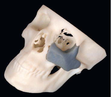
A medical model accurately corresponds to the image data and print resolution, and represents precisely the anatomical conditions of the patient ( Fig 5.2-2 ). Depending on the segmentation process, even combined hard- and soft-tissue models can be produced by using state-of-the-art printing processes with different material characteristics (multiple colors, transparency, different material properties).

2 History of 3-D printing technologies in CMF surgery
Before RP for medicine was introduced in the 1980s, its main field of application was in the aviation and automotive industry [Hull, 1986]. There was a strong need to produce realistic, solid prototypes or pre-series models of almost any shape and geometry. What once was a manual engineering process that consumed significant time and effort can be replaced with RP. Subsequently, RP technology spread quickly into various industrial sectors with great success. The fabrication process of realistic 3-D models in medicine could be established with the knowledge and experiences of professionals from the mechanical engineering field, combined with further development of modern radiological imaging technologies. At the end of the 1980s, the first reports on the production of medical models by using computer numerical control devices appeared ( Fig 5.2-3 ) [Brix et al, 1987].

The milling method then used had some major disadvantages and so an additive manufacturing process was introduced that eventually laid the foundation for the success of RP in the medical industry. Leading all 3-D printing processes in healthcare was stereolithography ( Fig 5.2-2 ), in which a 3-D model created on a computer is procured layer by layer by a laser beam in a liquid synthetic material bath.
Today a wide variety of 3-D printing technologies and appropriate services are available to fabricate 3-D models using additive or subtractive methods, forming hybrid solutions. Consequently, there is no limitation to one specific printing process.
3 Rapid prototyping technologies
Rapid prototyping is the process of printing realistic, physical 3-D prototypes designed and modified by a computer. These prototypes allow engineers, developers and physicians to visualize their designs and use them as physical models that can be felt and held. The RP models provide a valuable 3-D aid to the planning and design processes, and enable the transfer of a purely visual representation to a visual-tactile interaction called “touch to comprehend” [Petzold et al, 1999].
In the industrial and healthcare markets, many different RP/ rapid manufacturing production units are now available. Additionally, commercial 3-D printing services are offered by numerous service providers. With RP, subtractive manufacturing processes can be differentiated from additive manufacturing processes. As subtractive manufacturing techniques are mainly computer-controlled milling processes, they have gained a greater importance, particularly in the production of bio-models. The resulting model can be produced from a material block (eg, plastic, ceramic or metal) by a multi-axis milling machine. This technology is mainly used in the manufacture of patient-specific implants (eg, polyetheretherketone) or in the dental sector (eg, crowns and bridges). The polyurethane foam blocks ( Fig 5.2-3 ) used at the beginning of the RP era to produce skull models did not produce viable applications in CMF surgery, as this technique has significant limitations in the fabrication of closed model geometries, such as sinuses [Brix et al, 1987]. The various additive printing methods nowadays allow creation of an almost free and complex geometry. This results in highly accurate production of 3-D models with almost every conceivable type of material (eg, paper, plastics/polymers, ceramics, or metals) [Barazanchi et al, 2016].
Conventional additive printing processes include stereolithography, selective laser sintering or selective laser melting, fused deposition modeling (FDM) ( Fig 5.2-4 ), polyjet or multijet printing and several other 3-D printing technologies. With respect to the accuracy of the fabricated anatomical models, emphasis is rather on the quality of the data source (eg, the image data quality or layer thickness of the underlying CT data set) than the printing process itself.

3.1 Stereolithography
Stereolithography was one of the first RP technologies and additive manufacturing processes introduced in the engineering field in the 1980s. By using a computer-controlled ultraviolet laser beam, a transparent or colored liquid photopolymer resin in a vat is cured successively layer by layer to produce a physical, largely transparent 3-D model from a virtual 3-D data set. Even objects of different colors may be created by modulating the energy of the laser beam. In this way, anatomical models can be produced in numerous colors to label relevant and vulnerable anatomical structures, such as nerves, blood vessels or tooth roots. The 3-D models can be sterilized and used in the operating room.
The high cost of the stereolithography printers and related devices (ie, the photo-curable resins) are a significant drawback. However, more affordable compact consumer stereolithography printers were introduced in recent years, opening new opportunities to fabricate cost-effective anatomical RP models.
3.2 Selective laser sintering, selective laser melting
Selective laser sintering produces 3-D objects by tracing a high-powered laser beam across a bin filled with heat-fusible powder. The powder particles, such as polymers and even ceramics or metal (eg, titanium), fuse in a thin layer. Subsequently, an additional thin layer of powder is applied on top of the solidified layer and fused again by the laser beam, forming the 3-D object. Reinforced structures are unnecessary because support is ensured by the unfused easy-to-remove powdered source material at the boundaries. If the powder is fully melted (not sintered) and solidified completely, this process is called selective laser melting.
3.3 Fused deposition modeling or fused filament fabrication
The FDM/fused filament fabrication process is the most popular printing technique in the RP consumer market ( Fig 5.2-4 ), it can also be found in the expensive professional level segment. Moreover, FDM 3-D printers are affordable. The printing process is based on the liquefaction of thermo-softening plastic (thermoplastic) by heat and curing after application and cooling on a build platform. After hardening, the platform is lowered by a fraction of a millimeter in accordance of one print-layer thickness. The next layer of hot plastic is applied on top. This process repeats until the 3-D print task is completed. Some FDM printers have multiple print heads (extruders), so that multicolor models can be printed. Additionally, one extruder produces resolvable support structures that can easily be removed by a special solvent or even by water after the printing process.
3.4 PolyJet or MultiJet printing
Like the inkjet printing technique on a sheet of paper, a polyjet or multijet machine prints using an industrial print head with many small nozzles containing photosensitive liquid polymer on a flat build tray. The printed material layer is usually hardened with ultaviolet light. Afterward, the next layer is applied. With this technology, the production of different colored 3-D objects with different material properties (from soft to hard) is possible.
3.5 Other RP techniques
With respect to all printing techniques, it should be mentioned that the accuracy and production quality of 3-D objects is largely dependent on the image data quality of the 3-D object and not only on the 3-D printer itself.
Moreover, there are other 3-D printing technologies available on the market that are not covered in this chapter [Winder et al, 2005].
4 Production process of RP models
4.1 Image acquisition
The quality and accuracy of a RP model depends primarily on the quality of the underlying image data set. For this reason, the best possible image data should be obtained with only few imaging artifacts. The decisive factor is to choose the correct imaging method (mainly CT, MRI or CBCT, but also ultrasound imaging or scans) and to use a corresponding standardized scanning protocol ( Fig 5.2-5 ). For CT images, spatial resolution should be as high and the slice thickness should be as thin as possible (1 mm or less) to minimize partial volume effect and other artifacts in reconstruction, while always considering the radiation dose for the patient. Imaging artifacts in CT scanning from metallic dental fillings and other restorations around the occlusal plane can complicate the segmentation process and hide anatomical structures. To delineate the teeth correctly, the use of radiolucent bite splints during a CT scan is recommended by some authors. Ideally, the image data are stored as DICOM files in the picture archive and communications system (PACS) of the hospital and can be transferred to the segmentation workstation via the internet or intranet. Strict data protection and security protocols for data transmission must be implemented in this workflow [Bibb et al, 2010].

4.2 Segmentation/virtual reconstruction
The segmentation process is a critical and occasionally timeconsuming step in generating accurate 3-D objects for further processing. The use of specific segmentation methods for 3-D image reconstruction is essential to obtain a realistic medical model. There are many semiautomated or fully automated software solutions commercially available to enable the image transfer from a 2-D data volume to a 3-D model. The decisive factor is the segmentation of the relevant anatomical structures of the resulting object, which is generally bone or soft tissue. The virtual anatomical model can subsequently be modified with the help of appropriate software applications and can be prepared for the 3-D printing process. At this point, corresponding printer control files are created for each 3-D printer and are exported and imported into this device. The printer control files include information of the 3-D object with specific additional data required for the manufacturing process, such as information about material properties of the print material or the position of supporting structures, if needed ( Fig 5.2-6 ).

The decisive factor here is to identify the relevant anatomical structures needed and to differentiate hard tissues from adjacent soft tissues ( Fig 5.2-7 ).

One basic approach of image processing algorithms is called thresholding. The CT scans gray scale perimeters are defined and calculated corresponding to the relevant tissue ranges of Hounsfield units. With the resulting image information, a 3-D image can be created by volume rendering and several other current 3-D reconstruction techniques. At the end of the segmentation procedure, the completed 3-D object or several isolated 3-D structures of the underlying DICOM data set can be aligned to predefined reference planes. They are then exported (mostly as STL files), or, depending on the application used, further processed. Since high-resolution 3-D files demand large data storage capacity and processor performance for 3-D visualization and modeling, a data simplification process may be necessary.
4.3 Modeling, data modifications, and data export
Once the segmentation process has been completed and a 3-D (STL) data set is present, this can be manipulated and modified further with the appropriate software applications. These steps include, for example, virtual trimming or isolation of relevant anatomical areas, superimposing defect zones with the virtually mirrored, healthy opposite side of the skull, or just modeling and modification of anatomical structures. Additionally, if detailed information on occlusal contacts is needed (eg, in orthognathic surgery), the 3-D files can be merged after the segmentation process with data obtained by an intra-oral (surface) scanning device. Some software solutions provide “wizards” that guide the user through the modeling steps. The resulting 3-D object for printing is optimized, sliced and exported. Defective areas can then be corrected and the data size can be reduced. Finally, a printing control file is exported that contains all necessary information depending on the chosen RP process.
4.4 Model fabrication and post-processing
The production of 3-D objects is dependent on the specific printing process. Depending on the object size and desired accuracy, the 3-D printing time varies enormously. As a rule, the building materials are applied and/or cured layer by layer. Additional support structures help to manufacture overhanging, complex geometries ( Fig 5.2-8 ). Once the 3-D model production process is finished, the print object is removed from the building platform and post-processed. The coarseness of the surface is smoothed and supporting structures are removed. Finally, the 3-D model can be washed and sterilized depending on the print material. Life-size anatomical models may be used as a guide or as a bending template during the operation.

5 Applications of RP models in CMF surgery
The RP models can be used for preoperative planning and as an aid during surgery. Before the operation, the surgeon can plan the procedure with a realistic anatomical model ( Fig 5.2-9 ).
A model operation can be performed, if necessary, the bestfitting implants may be selected before surgery based on the patient’s anatomy. Plates can also be accurately prebent on the medical model ( Fig 5.2-10 ).

Alternative surgical approaches and minimally invasive surgical techniques may be considered and evaluated. Preoperative planning with medical RP models can shorten operative time. Ultimately treatment and follow-up costs can be saved compared with traditional surgical methods. The likelihood of complications can be reduced using RP models as a planning and guiding aid and they are valuable in the medical informed consent process. The operation can be shown and explained to the patient step-by-step using the anatomical RP model.
The RP models are helpful in student, resident and trainee education [Lambrecht et al, 2010]. Rare diseases, malformations or defects after trauma can be demonstrated based on these models. Surgical procedures can be practiced on RP models, especially if they are produced through cost-effective FDM manufacturing processes.
5.1 Anatomical models
Realistic, haptic 3-D models of patients’ anatomy represent a valuable tool throughout the entire treatment process from diagnosis to treatment planning, the surgical procedure and quality assurance ( Fig 5.2-11 ). Anatomical rapid prototyping models have not lost importance in CMF surgery, even in times of computer-based virtual surgical planning, intraoperative navigation and 3-D fabrication of patientspecific implants. Numerous studies have shown that the use of 3-D models in the surgical planning process and implementation not only leads to an improvement of precision in the treatment and prevention of errors but also to a reduction in the operating time. Additionally, 3-D models can help to choose minimally invasive surgical approaches and to practice critical surgical steps in the 3-D model for an optimized treatment outcome.

5.1.1 Surgical planning
Before actual surgery, 3-D printed anatomical models allow to perform all surgical steps realistically on the model itself. In addition, the appropriate surgical approach and the bestfitting implants can be selected preoperatively. These implants can be prebent and used after the sterilization process directly in the operating room when needed, thus guaranteeing precision, saving operation time and costs.
The 3-D printed plastic models can be sawn, drilled, plated, and supplemented by individually manufactured implants. These properties allow to achieve optimal surgical results by planning and practicing the intermediate steps of the procedure especially for complex surgical interventions.
5.1.2 Informed consent
The 3-D printed anatomical models can be used in the process of informed consent as a basis for discussion of the surgical procedure with the patient. They are descriptive, can be handled by the patient during the preoperative consultation and serve as a basis for further discussion ( Fig 5.2-12 ).

Especially before tumor operations or extensive reconstructive CMF surgery, 3-D models can be used to explain complex anatomical and procedural details in an understandable way to patients.
5.2 Traumatology
The use of 3-D printed models offers an advantage in the treatment of craniofacial fractures. However, it is crucial that both costs and time are considered in a reasonable way because acute trauma cases typically should be treated in a timely manner. If available, low-cost in-house printing speeds up manufacturing of the models.
The CT scans often are produced just after admission of patients in the emergency department. Subsequently, these radiological cross-sectional images can be used for the segmentation process and as print control files, as the basis to produce anatomical 3-D models. Additionally, it is important that the region of interest be focused as narrowly as possible to shorten the production time of the 3-D models to a few hours. With the use of suitable medically certified materials, 3-D printed models can be used after cleaning and sterilization directly in the operating room.
The appropriate selection and bending of implants, for example in complex mandibular conditions ( Fig 5.2-13 ), or adaption of titanium meshes for orbital wall fractures ( Fig 5.2-14 ), can save time in the operating room [Derand et al, 2009]. The use of prebent titanium plates may allow smaller, less invasive surgical approaches and can additionally serve as guides for fracture reduction and fixation. Individually, precontoured titanium plates and titanium meshes represent an accurate, cost-effective alternative to 3-D printed patient-specific implants.


5.3 Orthognathic surgery
Sagittal, vertical or transversal skeletal deformities can be corrected through various types of osteotomies of the maxilla and mandible. These procedures require careful preinterventional planning to create a stable occlusion, which plays a decisive role for this kind of surgery. With the help of 3-D models that can be combined with plaster models of the dentition, even complex surgery can be planned in a step-by-step fashion. The 3-D models show all relevant anatomical structures and help to prevent intraoperative errors ( Fig 5.2-15 ). Accordingly, the appropriate implants can be pre-selected and plates can be prebent before surgery. Prebent plates can serve as surgical guides or templates to facilitate the orientation and positioning of the upper and lower jaw during the operation [Shaheen et al, 2016].

5.4 Craniofacial surgery
The exact anatomical reproduction of congenital or acquired craniofacial deformities in children has made 3-D printed skull models an important tool for the planning of skull correction procedures in many craniofacial centers. The relevant and critical anatomical structures are visualized, and the complex surgical steps can be planned and simulated. With the help of these models, surgical guides can be manufactured, which allow surgery with high degree of precision ( Fig 5.2-16 ) [Seruya et al, 2013; Soleman et al, 2015].

5.5 Tumor surgery, pathology and adjunctive therapy
The 3-D models are useful in the planning of tumor resection and anatomical reconstructions. Color-coded 3-D models may visualize the extent of tumor infiltration and therefore allow precise planning of ablative surgery ( Fig 5.2-17 ). Precise anatomical reconstruction with prebent titanium plates and autogenous grafts or microvascular flaps can be achieved [Chopra et al, 2014]. Furthermore, 3-D anatomical models facilitate orientation and examination of histopathological specimens for pathologists. Resection borders can be marked accurately on the model for their reference ( Fig 5.2-18 ). Patient models are also used for radiation therapy as a discussion and planning basis.


5.6 Reconstructive surgery
For unilateral anomalies or defects in the facial area, the easiest way of reconstruction planning is the virtual mirroring of the healthy anatomical side. This serves as the basis for further planning steps, and for the prebending of titanium plates or the manufacturing of patient-specific implants. Additionally, they can serve as an orientation aid and surgical guide, and prevent misalignment of anatomical structures during the operative procedure ( Fig 5.2-19 ).

5.7 Distraction osteogenesis
For the planning of bone distraction, 3-D printed anatomical skull models ( Fig 5.2-20 ) are valuable to determine the position of the necessary osteotomies, and ultimately to select the best fitting bone distraction devices. All steps of the surgical procedure and the distraction process itself can be realistically visualized and rehearsed. The distractors can be fitted to the model before surgery.

6 Summary
Especially for complex problems, patient specific 3-D models are useful for both the planning process and intraoperatively. The use of medical models for planning improves quality and accuracy and reduces operating time and associated costs.
With the introduction of low-priced (consumer) printers in the market, cost-effective 3-D printing to produce planning and demonstration models will play an even bigger role in the field of medicine and surgery [Kamali et al, 2016].
With affordable in-house rapid manufacturing, time-consuming and expensive services provided by external companies can be avoided or limited to special indications. In addition to individual patient care, 3-D models can be used for patient information and surgical training. These models serve as illustrative materials and can be manipulated (sawn, drilled or plated) directly in surgical skill laboratories.
7 References and suggested reading
Barazanchi A, Li KC, Al-Amleh B, et al. Additive technology: update on current materials and applications in dentistry. J Prosthodontics. 2016 Sep 23;1–8. Bibb R, Winder J. A review of the issues surrounding three-dimensional computed tomography for medical modelling using rapid prototyping techniques. Radiography. 2010 Feb 1;16(1):78–83. Brix F, Lambrecht JT. [Preparation of individual skull models based on computed tomographic information.] Fortschr Kiefer Gesichtschir. 1987;32:74–77. German. Chopra K, Folstein MK, Manson PN, et al. Complex craniofacial reconstruction using stereolithographic modeling. Ann Plast Surg. 2014 Jan;72(1):59–63. Derand P, Hirsch JM. Virtual bending of mandibular reconstruction plates using a computer-aided design. Am Assoc Oral Maxillofac Surg. 2009 Aug 1;67(8):1640–1643. Hull CW. Apparatus for production of three-dimensional objects by stereolithography. Available at: http://www.google.nl/patents/US4575330. Accessed Mar 11, 1986. Kamali P, Dean D, Skoracki R, et al. The current role of three-dimensional printing in plastic surgery. Plast Reconstr Surg. 2016 Mar;137(3):1045–1055. Lambrecht JTH, Berndt D, Christensen AM, et al. Haptic model fabrication for undergraduate and postgraduate teaching. Int J Oral Maxillofac Surg. 2010 Dec 1;39(12):1226–1229. Petzold R, Zeilhofer HF, Kalender WA. Rapid protyping technology in medicine: basics and applications. Comput Med Imaging Graph. 1999;23:277–284. Seruya M, Borsuk DE, Khalifian S, et al. Computer-aided design and manufacturing in craniosynostosis surgery. J Craniofac Surg. 2013 Jul;24(4):1100–1105. Shaheen E, Sun Y, Jacobs R, et al. Threedimensional printed final occlusal splint for orthognathic surgery: design and validation. Int J Oral Maxillofac Surg. 2016 Nov 1;1–5. Soleman J, Thieringer F, Beinemann J, et al. Computer-assisted virtual planning and surgical template fabrication for frontoorbital advancement. Neurosurg Focus. 2015 May;38(5):E5. Winder J, Bibb R. Medical rapid prototyping technologies: state of the art and currentlimitations for application in oral and maxillofacial surgery. J Oral Maxillofac Surg. 2005 Jul;63(7):1006–1015.
5.3 Navigation and computer planning in craniomaxillofacial reconstruction
5.3.1 Navigation and computer planning in craniomaxillofacial reconstruction—introduction
Computer-assisted techniques have given advanced craniomaxillofacial (CMF) surgery great momentum toward better quality of all steps of the process, including preoperative planning, intraoperative execution, and postoperative quality control. Today even a personal computer has enough calculation power to deal with full-skull Voxel-based data sets (computed tomography [CT], cone beam CT, and magnetic resonance imaging). In the following chapters all aspects of extended use of Voxel-based data sets for the CMF surgeon are described. Analysis of virtual models and biomodels, intraoperative navigation, intraoperative imaging are more technique-related topics and are described in the first part of the following chapters. Process implementation into clinical relevant digital workflow is addressed in the second part.
Besides providing more information for the surgeon, the whole team will benefit from image-analyzing software that allows, independent of the anatomical region, a common trunk data set evaluation and decision making. The impact for teaching, documentation, and interspecialty cross-information is tremendous as visualization allows a languageindependent communication.
Computer assistance allows visualization of deformities and defects, creation and visualization of planned reconstructions, and intraoperative visualization of the reconstruction plan. Since all this is accompanied by no further radiation but just the extended use of the required preoperative Voxel-based data set, the following chapters encourage CMF surgeons to take advantage of this breathtaking new development in the field of reconstructive CMF surgery.
5.3.2 Image analysis: data acquisition and processing
1 Introduction
Computer-aided surgical simulation (CASS) nowadays is an important aid in safe and predictable craniomaxillofacial (CMF) surgical reconstruction in a number of clinical applications, including complex maxillofacial trauma [Bell et al, 2009; Bell, 2010; Bell et al, 2010; Bui et al, 2012; Fuller et al, 2007; Gellrich et al, 2002; Markiewicz et al, 2011; Schmelzeisen et al, 2004], head and neck oncological surgery [Bell et al, 2010; Durbin et al, 2005; Gelesko et al, 2012; Gregoire et al, 2011; Hamilton et al, 2012; Hsu et al, 2012; Schramm et al, 2000; Lubbers et al, 2010, To et al, 2002], orthognathic surgery [Bell, 2011; Gateno et al, 2003, 2007, and 2011; Hamilton et al, 2012; Hsu et al, 2012; Xia et al, 2007, 2009, 2011], and temporomandibular joint surgery [Chandran et al, 2011; Schmelzeisen et al, 2002; Yeung et al, 2006; Yu et al, 2009]. Also known as “virtual surgery”, CASS can be divided into four phases: (1) data acquisition phase, (2) planning phase, (3) surgical phase, and (4) assessment phase. While there may be some special adjustments based on the specific clinical application, the principles are consistent and are outlined below.
2 Data acquisition phase
A careful clinical examination is an essential part of the data acquisition phase. This is ideally complemented by digital photographic documentation of the facial structures in multiple views, as well as intraoral and occlusal views. Highresolution, thin cut (1 mm) computed tomography (CT) imaging or cone beam CT is obtained for purposes of computer-aided surgical simulation. Low-resolution or wide cut CT scans, which are typically obtained as part of a trauma patient’s initial survey, offer a poor representation of the thin-walled orbits and paranasal sinuses and are inadequate for CASS. The high-resolution CT or cone beam CT scan data will be stored in DICOM (digital information and communications in medicine) format. The DICOM data are then imported into a proprietary computer-aided design/computer-aided manufacturing (CAD/CAM) software program.
3 Presurgical planning phase
The presurgical planning phase consists of the analysis of the newly formatted CT data in 3-D, segmenting out the altered portions of the facial skeleton, or using the mirror image of the unaffected side to overlay the deformed portions of the affected facial skeleton. The planning phase differs greatly and depends on the portions of the maxillofacial skeleton that are deformed or missing and the type of reconstruction planned. For instance, in orbital fractures a critical measure of successful reconstruction is the restoration of the orbital volume, whereas in isolated zygomaticomaxillary complex fractures successful reconstruction is largely based on the restoration of the bizygomatic width and facial projection. Restoration of dental occlusion as well as mandibular width, height, and projection are key goals in cases of comminuted mandibular fractures. In general, standardized measurements can be used to segment the fractured portions of the facial skeleton and plan the reconstruction. This part of the surgical planning can either be performed by the surgeon, or alternatively via a web meeting that can be set up with a third-party company in which a computer planning specialist assists the surgeon in manipulating the CT data for the planned reconstruction. Once the surgical plan is finalized, the proprietary software data plan should be back-converted. Back-conversion specifically refers to translating the surgical data plan created by the proprietary software “back” to the standard DICOM format. This DICOM format may then be viewed on workstations not loaded with the proprietary software, and it allows interoperability between the planning software and intraoperative navigation systems.
4 Surgical phase
During the surgical phase, the virtual surgical plan is translated to the patient’s situation using a combination of stereolithographic models, cutting guide stents, and/or intraoperative navigation. Stereolithographic models are particularly useful for severely comminuted fractures and panfacial fractures, as they allow for preoperative plate bending and decrease of operating room time. Cutting guide stents in maxillofacial surgery are most useful for reconstruction of head and neck tissues after tumor resection and secondary reconstruction of posttraumatic deformities. They are less useful in the acute setting where the bones can still be mobilized into adequate reduction. Intraoperative navigation is particularly useful for real-time assessment of facial width and projection when repairing zygomaticomaxillary complex fractures and for the evaluation of plate placement during repair of orbital floor and medial orbital wall fractures [Fuller et al, 2007].
5 Assessment phase
The assessment phase has historically consisted of the clinical examination with or without conventional postoperative CT imaging. Modern mobile CT or cone beam CT scanners have more recently facilitated intraoperative quality control by allowing this in the operating room with the patient still under anesthesia. With an intraoperative CT scan the actual surgical result can be compared with the presurgical plan, allowing for immediate surgical correction if indicated. Intraoperative assessment of facial projection, facial width, and orbital volume, as well as correct facial proportions (height, width, projection) or jaw position can be performed, allowing for improved predictability and fewer corrective procedures.
6 References and suggested reading
Bell RB, Markiewicz MR. Computer-assisted planning, stereolithographic modeling, and intraoperative navigation for complex orbital reconstruction: a descriptive study in a preliminary cohort. J Oral Maxillofac Surg. 2009 Dec;67(12):2559–2570. Bell RB. Computer planning and intraoperative navigation in craniomaxillofacial surgery. Oral Maxillofac Clin North Am. 2010 Feb;22(1):135–156. Bell RB, Weimer KA, Dierks EJ, et al. Computer planning and intraoperative navigation for palatomaxillary and mandibular reconstruction with fibular free flaps. J Oral Maxillofac Surg. 2010 Mar;69(3):724–732. Bell RB. Computer planning and intraoperative navigation in orthognathic surgery. J Oral Maxillofac Surg. 2011 Mar;69(3):592–605. Bui RG, Bell RB, Dierks EJ. Technological advances in the treatment of facial trauma. Atlas Oral Maxillofac Surg Clin North Am. 2012 Mar;20(1):81–94. Chandran R, Keeler GD, Christensen AM, et al. Application of virtual surgical planning for total joint reconstruction with a stock alloplast system. J Oral Maxillofac Surg. 2011 Jan;69(1):285–294. Durbin MG, Sonnenburg RE, Melroy CT, et al. Staged endoscopic and combined open/endoscopic approach in the management of inverted papilloma of the frontal sinus. Am J Rhinol. 2005 Sep-Oct;19(5):442–445. Fuller SC, Strong EB. Computer applications in facial plastic and reconstructive surgery. Curr Opin Otolaryngol Head Neck Surg. 2007 Aug;15(4):233–237. Gateno J, Xia JJ, Teichgraeber JF. New 3-dimensional cephalometric analysis for orthognathic surgery. J Oral Maxillofac Surg. 2011 Mar;69(3):606–622. Gateno J, Xia JJ, Teichgraeber JF, et al. Clinical feasibility of computer-aided surgical simulation (CASS) in the treatment of complex cranio-maxillofacial deformities. J Oral Maxillofac Surg. 2007 Apr;65(4):728–734. Gateno J, Xia JJ, Teichgraeber JF. Effect of facial asymmetry on 2-dimensional and 3-dimensional cephalometric measurements. J Oral Maxillofac Surg. 2011 Mar;69(3):655–662. Gateno J, Xia J, Teichgraeber JF, et al. A new technique for the creation of a computerized composite skull model. J Oral Maxillofac Surg. 2003 Feb;61(2):222–227. Gellrich NC, Schramm A, Hammer B, et al. Computer-assisted secondary reconstruction of unilateral posttraumatic orbital deformity. Plast Reconstr Surg. 2002 Nov;110(6):1417–1429. Gelesko S, Markiewicz MR, Weimer K, et al. Computer-aided orthognathic surgery. Atlas Oral Maxillofac Surg Clin North Am. 2012 Mar;20(1):107–118. Gregoire C, Adler D, Madey S, et al. Basosquamous carcinoma involving the anterior skull base: a neglected tumor treated using intraoperative navigation as a guide to achieve safe resection margins. J Oral Maxillofac Surg. 2011 Jan;69(1):230–236. Hamilton T, Markiewicz MR, Jarman J, et al. Dental outcomes in computer-assisted orthognathic surgery. J Craniofac Surg. 2012 May;23(3):e223–226. Hsu SS, Gateno J, Bell RB, et al. Accuracy of a computer-aided surgical simulation protocol for orthognathic surgery: a prospective multicenter study. J Oral Maxillofac Surg. 2013 Jan;71(1):128–142. Lubbers HT, Jacobsen C, Konu D, et al. Surgical navigation in cranio-maxillofacial surgery: an evaluation on a child with a cranio-facio-orbital tumour. Br J Oral Maxillofac Surg. 2011 Oct;49(7):532–537. Markiewicz MR, Dierks EJ, Potter BE, et al. Reliability of intraoperative navigation in restoring normal orbital dimensions. J Oral Maxillofac Surg. 2011 Nov;69(11):2833–2840. Markiewicz MR, Dierks EJ, Bell RB. Does intraoperative navigation restore orbital dimensions in traumatic and post-ablative defects? J Craniomaxillofac Surg. 2012 Feb;40(2):142–148. Markiewicz MR, Bell RB. The use of 3D imaging tools in facial plastic surgery. Facial Plast Surg Clin North Am. 2011 Nov;19(4):655–682. Schmelzeisen R, Gellrich NC, Schramm A, et al. Navigation-guided resection of temporomandibular joint ankylosis promotes safety in skull base surgery. J Oral Maxillofac Surg. 2002 Nov;60(11):1275–1283. Schmelzeisen R, Gellrich NC, Schoen R, et al. Navigation-aided reconstruction of medial orbital wall and floor contour in cranio-maxillofacial reconstruction. Injury. 2004 Oct;35(10):955–962. Schramm A, Gellrich NC, Gutwald R, et al. Indications for computer-assisted treatment of cranio-maxillofacial tumors. Comput Aided Surg. 2000;5(5):343–352. To EW, Yuen EH, Tsang WM, et al. The use of stereotactic navigation guidance in minimally invasive transnasal nasopharyngectomy: a comparison with the conventional open transfacial approach. Br J Radiol. 2002;75:345–317. Xia JJ, Gateno J, Teichgraeber JF. New clinical protocol to evaluate craniomaxillofacial deformity and plan surgical correction. J Oral Maxillofac Surg. 2009 Oct;67(10):2093–2106. Xia JJ, Gateno J, Teichgraeber JF, et al. Accuracy of the computer-aided surgical simulation (CASS) system in the treatment of patients with complex craniomaxillofacial deformity: a pilot study. J Oral Maxillofac Surg. 2007 Feb;65(2):248–254. Xia JJ, McGrory JK, Gateno J, et al. A new method to orient 3-dimensional computed tomography models to the natural head position: a clinical feasibility study. J Oral Maxillofac Surg. 2011 Mar;69(3):584–591. Xia JJ, Shevchenko L, Gateno J, et al. Outcome study of computer-aided surgical simulation in the treatment of patients with craniomaxillofacial deformities. J Oral Maxillofac Surg. 2011 Jul;69(7):2014–2024. Yeung RW, Xia JJ, Samman N. Image-guided minimally invasive surgical access to the temporomandibular joint: a preliminary report. J Oral Maxillofac Surg. 2006 Oct;64(10):1546–1552. Yu HB, Shen GF, Zhang SL, et al. Navigation-guided gap arthroplasty in the treatment of temporomandibular joint ankylosis. Int J Oral Maxillofac Surg. 2009 Oct;38(10):1030–1035.
5.3.3 Virtual models and segmentation
1 Introduction
Virtual models are useful when replacing lost hard-tissue structures of the skull after trauma or ablative tumor surgery. Rapid prototyping procedures like computer-assisted design and manufacturing (CAD/CAM) have dramatically improved surgical strategies in reconstructive surgery of the craniomaxillofacial skeleton [Rana et al, 2012]. Coupling preoperative planning with navigation systems facilitates symmetric bone repositioning and replacement. Before surgery virtual models are segmented out of the DICOM data using appropriate techniques, such as manual segmentation, threshold-based segmentation, or segmentation using the Smartbrush algorithm.
2 Manual segmentation
In manual segmentation, the desired structure is outlined by hand. Based on the gray scale of magnetic resonance imaging scans or Hounsfield units in computed tomographic (CT) scans, the computer automatically recognizes margins of the desired structures. This procedure is time-consuming and can lead to an inadequate segmentation quality if there are areas of poor contrast within the DICOM data. Due to these issues, this segmentation technique is generally not used on a daily clinical routine [Rana et al, 2014] ( Fig 5.3.3-1 ).

3 Threshold segmentation
Segmentation can be achieved using a range of Hounsfield units in a CT or gray scale in other imaging modalities. To limit segmentation to certain areas, a region of interest (ROI) should be defined before the process. Only areas within the predefined range are then automatically selected. The main disadvantage of this method is incorrect segmentation of tissue within the same range of Hounsfield units or gray scale in the vicinity of the desired object [Rana et al, 2014].
4 3-D Smartbrush
Segmentation using the new Smartbrush technique is started by selecting a few points inside the desired area. Around these points, ROI is automatically defined and the final 2-D segmentation is then computed by a region-growing algorithm.
This method of segmentation can then either be conducted for each slice or by the 3-D interpolation of the program itself. The 3-D interpolation algorithm automatically detects the 3-D ROI and segments the designated area with a regiongrowing algorithm. Smoothing the created object is the last step of the segmentation process. Besides segmenting hard tissue, this method can also segment other anatomical regions like contents of the orbit, which may be available for reconstruction planning. Additionally, segmented structures can be modified by elastic deformation of the selected object using the conventional smart shaper ( Fig 5.3.3-2 ).

5 Clinical use of virtual models
In trauma cases, anatomical structures can easily be segmented using an automatic, atlas-based algorithm ( Fig 5.3.3-3 ). The central task of such an algorithm is to find a one-to-one correspondence between the patient’s data set and a predefined data set from an atlas containing several anatomical templates. The structures are segmented automatically by elastic deformation of the templates to match the patient’s anatomy as precisely as possible. Using the acquired data, cutting and drilling guides for intraoperative use can easily be manufactured within a few days.

In ablative surgery, 3-D (voxel-based) data sets allow to estimate the extension of head and neck tumors. As a tumor is not a normal structure within a patient’s anatomy, it cannot be automatically segmented using an atlas. Preoperatively, the tumor margins are therefore most commonly outlined manually using different instruments, such as brushing. After this step of planning, anatomical structures and a target region for tumor resection or taking biopsies are clearly defined. The rendered virtual models can then be transferred into DICOM format to communicate patientspecific tumor information (invasion into vessels, nerves, or skull base) to the oncologist, radiotherapist, and pathologist for further oncological treatment.
6 References and suggested reading
Rana M, Essig H, Eckardt AM, et al. Advances and innovations in computer-assisted head and neck oncologic surgery. J Craniofac Surg. 2012;23(1):272-278. Rana M, Modrow D, Keuchel J, et al. Development and evaluation of an automatic tumor segmentation tool: a comparison between automatic, semi-automatic and manual segmentation of mandibular odontogenic cysts and tumors. J Craniomaxillofac Surg. 2014 Apr;43(3):355–359.
5.3.4 Biomodels
1 Introduction
Biomodels can be divided into standard ones that are not patient specific ( Fig 5.3.4-1 ) and individual ones that are derived mainly from patients’ computed tomographic (CT) data. In addition to the visual assessment of a CT scan, the haptic option provided by a patient’s specific biomodel can reveal concealed anatomical information. Models created by computer-assisted design and manufacturing (CAD/CAM) not only support medical diagnosis and surgical treatment planning but may also improve communication with the patient [Schramm et al, 2009].

2 Patient-specific biomodels
Rapid prototyping techniques are used to print out patientspecific 3-D biomodels from CT and cone beam-CT data. The most common material used for the rapid prototyping process is polyamide. Variants or hybrids are commercially available with different fillers like glass, carbon-fiber, carbon, and aluminum. Depending on the production process, the models are not necessarily monochrome. Meanwhile anatomical regions of interest like tumors, vessels, or nerves can be highlighted by different colors. For intraoperative use in a sterile environment, it is of crucial importance that the material is autoclavable. This is inevitably necessary for osteotomy guides that enable the accurate transfer of the virtual plan to the operating room.
By using the CT scan data, the actual patient’s anatomy can be physically reproduced in a 3-D model. However, more interesting than the reproduction of defects or deformities is the fabrication of a true to original skull model where bone defects and deformities are already individually corrected. The remarkable advance in virtual 3-D planning allows the modification of the CT data by using different algorithms based on mirrored or rigid and elastic deformations. The entire or even partial printout of a reconstructed skull model may serve as a mold at which the osteosynthesis materials can be individually prebent [Kokemuller et al, 2011]. For example, for the reconstruction of the midface or the calvarium 3-D titanium meshes can be used and for bridging mandibular defects titanium plates are suitable. The fit of the prefabricated CAD/CAM implants and osteotomy guides can easily be tested preoperatively on the patient’s original nonmodified (osteotomy guides) as well as on the modified biomodels (implants) ( Fig 5.3.4-2 ).

3 Summary and outlook
The appeal of the present workflow is that analysis, planning, and manufacturing of implants to restore the craniofacial skeleton is completely controlled by the surgeon. Meanwhile, several companies offer on-line services to design customized implants derived directly from the patients’ CT data. Since in this workflow molding models are no longer required, the surgeon has to collaborate closely with a specially trained clinical engineer throughout the CAD of the implant [Essig et al, 2011]. Actual developments in simulation software pave the way for a model-free automatized design and manufacture of biocompatible patient-specific implants by the surgeon himself.
4 References and suggested reading
Essig H, Rana M, Kokemueller H, et al. Pre-operative planning for mandibular reconstruction: a full digital planning workflow resulting in a patient specific reconstruction. Head Neck Oncol. 2011;3:45. Kokemuller H, von See C, Essig H, et al. [Rekonstruktion komplexer Mittelgesichtsdefekte durch individualisierte Titanimplantate]. HNO. 2011;59:319-326. German. Schramm A, Suarez-Cunqueiro M, Rucker M, et al. Computerassisted therapy in orbital and midfaci al reconstructions. Int J Med Robot Comput Assist Surg. 2009;5:111-124.
5.3.5 Intraoperative navigation
1 Introduction
Navigation technology was incorporated into surgical treatment, initially in neurosurgery, to find specific structures within a volume of tissue, ie, to localize an intracranial tumor [Guijarro-Martinez et al, 2014]. Navigation was introduced into craniomaxillofacial (CMF) surgery when segmentation of data sets became feasible, virtual modeling could occur and digital blueprints resembling the ideal bone reconstruction could be created [Schramm et al, 2008]. The latter means that the breakthrough of navigation for CMF surgeons is because a virtual plan can be visualized intraoperatively by using radiation-free navigation.
2 Navigation systems
Today several navigation systems are available ( Table 5.3.5-1 ; Fig 5.3.5-1 and Fig 5.3.5-2 ) [Rana et al, 2012]. Navigation systems include a computer that is linked to a detection device. This allows tracking of the position of the patient on the operating table by an infrared camera and instruments that are used for surgery. To achieve intraoperative navigation, the patient on the operating table must be matched with the virtual patient represented by the Voxel-based data set in the navigation system ( Fig 5.3.5-3 ) [Rana et al, 2012; Zizelmann et al, 2007; Schmelzeisen et al, 2004].


|
Technique |
Company |
Navigational system |
|
Optical |
Medtronic |
Stealth Station |
|
IVS Technology |
Voxim |
|
|
|
Stryker |
eNlite |
|
NavSuite |
BrainLab |
|
|
Kolibri, Kick |
Dual Curve |
|
|
XIONmedical |
Matrix Polar |
|
|
Collin |
DigiPointeur |
|
|
Fiagon |
CMF-System |
|
|
Electromechanical |
ISG Technologies |
Viewing wand |
|
Electromagnetical |
Visualization Technology |
Insta Trak |
|
|
BrainLab |
Kick-EM |
|
Fiagon |
ENT-EM |
|
|
|
Stryker |
Scopis-Hybrid |
|
Ultrasound based |
Sono Wand |
Invite |
3 Clinical application
To detect the patient’s position, the so-called dynamic reference frame or array is fixed to the patient’s head, either via an attachment on the Mayfield clamp ( Fig 5.3.5-4 ), directly screw-retained on the skull of the patient or a headband attachment ( Fig 5.3.5-5 ) [Schmelzeisen et al, 2004]. Registration is based on either preoperative defined landmarks, laser scanning methods or so-called navigation markers that can be either glued to the surface (eg, skin markers, with less accuracy) or hard tissue borne with more accuracy, eg, cruciform bone-anchored screws or cruciform screws mounted on a dental splint (in partially or completely dentated patients) ( Fig 5.3.5-6 ) [Gellrich et al, 2002; Essig et al, 2011].


Either of these markers has to be implemented into the scanning protocol of the preoperative Voxel-based data set so that the same structures can be defined on the real patient intraoperatively and on the Voxel-based data set [Essig et al, 2011]. The exception to this is the anatomical landmark-based registration only or the laser surface scanning registration; these latter techniques lack accuracy in long-lasting craniofacial surgeries requiring extensive bone work and especially in cases where re-registration is needed, and coronal flaps have been raised. As a rule of thumb: hard tissue-borne navigation markers are preferred [Rana et al, 2012].
Two different navigation principles can be used, optical systems or electromagnetic systems. For reconstructive CMF surgery, the major experience exists with infrared-based optical navigation systems where a set of cameras is mounted to a mobile stand, which can detect the position of the patient and the instruments in space. Basic components of the setup for intraoperative navigation are the navigation unit, the camera, and the patient on the operating table with a reference device ( Fig 5.3.5-7 ) [Rana et al, 2012; Gellrich et al, 2002; Essig et al, 2011].

Stay updated, free dental videos. Join our Telegram channel
VIDEdental - Online dental courses


