Q. 2. Discuss in detail factors responsible for obtaining an ideal radiograph.
Or
What is an ideal radiograph? Enumerate the various factors influencing the quality of radiograph.
Or
Define an ideal radiograph. Describe basic principles to obtain an ideal radiograph.
Ans.
• A visible photographic record on the X-ray film produced by passage of X-rays through an object or body is called radiograph.
• Dental radiograph is a photographic image produced on the film by the passage of X-rays through teeth and related structures.
According to HM Worth’s words, “An ideal radiograph is one which has desired density and overall blackness and which shows the part completely without distortion with maximum details and has the right amount of contrast to make the details fully apparent”.
The characteristics of an ideal radiograph are as follows:
The image quality and the amount of detail shown on a radiographic film depend on several factors mentioned above and described in detail below:
Visual characteristics
First-degree factors:
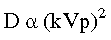
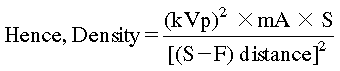
c. Operating kilo-voltage peak (kVp)
• An increase in milliamperage produces more X-rays that expose the film and result in increased film density.
• If mA increases, then film density increases. If mA decreases then film density decreases. Thus density varies directly and proportional to the milliamperage or the tube current.
• An increase in the exposure time increases the film density. If exposure time is increased, then film density is increased and if exposure time is decreased, then film density is decreased.
• Exposure time and milliamperage are interchangeable and are thus considered as a single factor.
Second-degree factors:
• In a patient with an increased amount of soft tissue or thick dense bones, fewer X-rays will reach the film and the radiograph will appear light and have less density.
• If subject thickness increases, then density decreases. If subject thickness decreases, then density increases.
• Adjustments in the operating mA, kVp or exposure time can be made to compensate for variations in size of the patient and subject thickness. The next lower kVp and/or mA should be used, if patient is thin and has a narrow facial bone structure.
• Film speed: High-speed films require less mA/s in order to obtain a density change.
• Film latitude: It is measured as a range of exposures that can be recorded as distinguishable densities on a film.
• Radiographic noise: It is the appearance of uneven density of a uniformly exposed radiographic film. It is seen on a small area of film as localized variations in density.
d. Screens: Use of screens requires less mAs in order to obtain a density change.
e. Grids: The use of grids requires more mAs in order to obtain a density change.
f. Amount of filtration used: Reduction in the amount of added filtration used will increase the density.
g. Fog: Film fog may result in an undesirable form of darkening of the film.
Characteristic curve
• Hurter and Driffield first described the relationship between film density and exposure in 1890.
• A graphical relationship between film density and exposure is called a characteristic curve or Hand D Curve.
• This curve is typical of a screen-film combination, and reveals information about film contrast, speed, and latitude.
• It can be seen from the curve that as exposure is increased, density also increases.
The film has greatest diagnostic value, at the relatively straight portion of the graph.
• The difference in the degree of blackness (densities) between adjacent areas on a dental radiograph is known as contrast.
• A radiograph is said to have a ‘high contrast’ if a dental radiograph has very dark areas and very light areas, as the dark and the light areas are strikingly different.
• A radiograph that does not have very dark and very light areas, but instead has many shades of grey is said to have a ‘low contrast’.
• Radiographic contrast, i.e. the final visual difference between the various black, white, and grey shadows depends on:
• The difference caused by different degrees of attenuation as the X-ray beam is transmitted through different parts of the patient’s tissues is known as subject contrast.
Geometric characteristics
The main causes of loss of edge definition include:
A certain degree of unsharpness is present in all dental radiographs. The fuzzy, unclear area that surrounds a radiographic image is termed ‘penumbra’.
• Geometric unsharpness: This type of unsharpness is due to criss-crossing of rays at the edges of the object, resulting in a fuzzy image border. Size of the focal spot and target object distance affect geometric unsharpness.
• Size of the focal spot: Smaller the focal spot, sharper the image produced. When a “point source” is used, the normal focal spot size is 0.6 mm2 to 1 mm2 and nonsharpness is produced.
• Object–film distance: This should be as small as possible to get a sharper image.
• Target–object distance: Should be as large as possible, to get a sharper image.
• Motion unsharpness: It is caused by the patient moving during the exposure
• Absorption unsharpness: It is caused due to variation in object shape, e.g. cervical burn-out at the neck of a tooth.
• Screen unsharpness: It is caused by the diffusion and spread of the light emitted from intensifying screens.
• Poor resolution: Resolution is determined mainly by characteristics of the film including: type, direct or indirect action, speed, and silver halide emulsion crystal size.
• Image magnification refers to a radiographic image that appears larger than the actual size of the object it represents.
• Magnification or enlargement of a radiographic image results from the divergent paths of the X-ray beam. Because of this some degree of image magnification is present in every dental radiograph.
• The image magnification on a dental radiograph is influenced by the following:
• The distance between the source of X-rays and the film is known as the target–film distance also known as the source-to-film distance.
• When a longer position indicating device (PID) is used, more parallel rays from the middle of the X-ray beam strike the object rather than the diverging X-rays from the periphery of the beam. As a result, a longer PID and target–film distance result in less image magnification, and a shorter PID and target–film distance result in more image magnification.
• The distance between the object being radiographed, i.e. the tooth and the dental X-ray film is known as the object–film distance.
• A decrease in object–film distance results in a decrease in magnification, and an increase in object–film distance results in an increase in image magnification.
The factors influencing dimensional distortion of a radiographic image are:
• To minimize dimensional distortion, the X-ray beam must be directed perpendicular to the tooth and the film.
• If the vertical angulation is increased, there will be shortening of the image and if it is decreased, there will be elongation of the image.
• If the horizontal angulation is increased mesially or distally, there will be overlapping of structures.
• The geometric accuracy of any image depends upon the position of the X-ray beam, object, and image receptor satisfying certain basic geometrical requirements:
Alterations in geometric characteristics are mainly due to:
• X-rays originate from a definite area rather than a point source.
• X-rays travel in diverging straight lines as they radiate from their source of origin.
• Dental radiographs are a two-dimensional representation of three-dimensional structures. This results in unequal magnification of different parts of an object, because of the varying distances of these parts from the film.
Anatomic accuracy of radiographic images
Adequate coverage of the anatomic region of interest:
• It is important that the area of interest is well covered in the radiograph. Adequate coverage of the area of interest depends upon following factors:
Q. 4. Discuss “faulty intraoral(IO) radiographs”.
Ans.
Stay updated, free dental videos. Join our Telegram channel
VIDEdental - Online dental courses


