Radiography
Radiography is a basic tool of clinical medicine and dentistry that is used for routine diagnostic purposes. In that context, restorative and prosthetic materials – even other foreign bodies – may well be present. It is appropriate therefore to consider the factors which influence the appearance of structures in radiographic images. The physics of this is discussed with a view to a better understanding of the images obtained as well as the control that may be exercised in the process.
A brief indication of the aspects of atomic structure associated with the formation and absorption of X-rays is followed by an outline of the practical means of generating X-radiation and the type of spectrum thus obtained.
The critical issues centre on the differential absorption of X-radiation according to the elements present, the laws expressing these effects, and the need for filtration. The contributions of true absorption and scattering processes are distinguished and some of the practical implications are described.
Radiographic film has been the main means of recording such images, so it is necessary to explore the generation and properties of the image with respect to exposure as well as explain the terminology. Practical aspects of the handling and interpretation of the image (in a non-diagnostic sense) are presented. The utility and limitations of intensifying screens are outlined. However, alternative techniques are displacing film in favour of digitial images.
In terms of handling, image interpretation and radiological protection it is clearly important to understand the nature of X-radiation and its interaction with matter. It is this interaction that ties the subject to dental and biomedical materials. No distinction can be drawn in this sense between biological tissues and the foreign materials that may be present, but the discrimination of the two may be critical.
Radiography is a procedure used both clinically and industrially to obtain information non-destructively about the internal structure of objects. While the anatomical interpretation of clinical radiographs is of no concern here, that interpretation depends ultimately on the interaction of radiation with matter, both in the object being investigated and in the recording medium. That brings radiography firmly within the ambit of materials science. It is therefore considered important that these interactions be considered as an adjunct to understanding the interpretation process, especially since non-biological materials will frequently be present in the field, e.g. if any prior restorative treatment has been done.
§1 Atomic Structure
As was noted in 24§6, electromagnetic radiation may interact with matter in a variety of ways, depending on the wavelength of that radiation. So-called X-rays1 are associated with changes in the energy of inner electrons.
The electron configuration of an atom, that is, the distribution of the electrons among the various available orbitals 1s, 2s, 2p and so on, is governed by the Aufbau Principle. This effectively says that in filling the available set of atomic orbitals the electrons are placed in order of decreasing stability, with the added proviso of the Pauli Exclusion Principle. This states that no two electrons in one atom may have identical sets of quantum numbers. In other words, under normal conditions in the ground state the inner shells are all completely filled; there are no gaps.
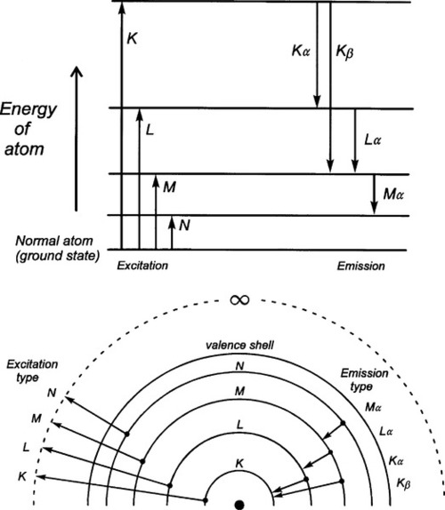
However, any electron may be removed from its orbital by the provision of a quantum of sufficient energy. In general the energy required corresponds to what has become known as the X-ray region of the electromagnetic spectrum, and the deeper the shell from which the electron was removed the higher the energy state of the atom which remains. Having thus excited the atom, any outer electron may fall down into the vacancy, and in so doing it will emit a quantum of radiation of energy corresponding to the energy difference between the two states of the atom. This quantum is known as a characteristic X-ray. If the original ejected electron is from the lowest energy shell, the K-shell, and an electron from the next lowest shell, the L-shell, falls into it, the characteristic X-ray is known as Kα radiation. If the K-shell vacancy is filled by an M-shell electron, the Kβ radiation is seen, and so on. A similar series of transitions to the L-shell results in L-series spectral lines. The processes involved are shown schematically in Fig. 1.1.
It should be apparent that in attempting to remove a given electron (and thus, incidentally, ionizing the atom), unless enough energy is provided to correspond with the energy of the transition, or somewhat more, no absorption of that energy can occur. Thus, at a supplied energy just below this critical absorption wavelength that particular electron cannot be ejected, although others in higher shells may be. This is one of the consequences of the quantization of radiation. The energy of the critical absorption wavelength is enough to remove the electron to infinity, but then be at rest. Any energy in excess of that exact amount must appear as the electron’s kinetic energy.
§2 X-ray Generation
What was described in §1 has to do with the atom specific effects of the absorption and emission of X-radiation. In particular, for absorption, it presupposes that there is a source of radiation of appropriate energies for those electron transitions to occur. We now describe the means of generating such radiation, and this is in a non-specific manner.
•2.1 Energy
Free electrons may absorb or emit radiation if they are accelerated or decelerated. They may be stopped by striking an atom or atoms, losing energy successively with each impact, and they may be accelerated or decelerated by an electric field. If an electron is accelerated over an electric field with voltage difference V between the start and end points, irrespective of the distance between those two points the kinetic energy E of the electron is then given by
< ?xml:namespace prefix = "mml" ns = "http://www.w3.org/1998/Math/MathML" />

where e is the electronic charge. This energy corresponds to electromagnetic radiation with wavelength λ:

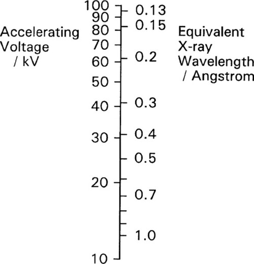
where h is Planck’s constant and c is the speed of light. This is in fact the energy of the quantum that would be emitted if the electron were brought to an abrupt halt. The relationship between accelerating voltage and wavelength may conveniently be given by:
where λ is in Angstroms if V is in kilovolts (kV) (Fig. 2.1). X-ray wavelengths are traditionally expressed in Angstrom2 units (Å). Currently this persists, even though it is not an S.I. unit. The equivalence is 1 Å = 0.1 nm. It is worth nothing here that the energy unit, the electron volt (eV), commonly used in this kind of context, is defined by equation 2.1. Thus 1 keV is equivalent to passing through a 1 kV field, whatever the distance this requires.
•2.2 Spectrum
Normally the total kinetic energy of the decelerated electron will only very rarely be converted into precisely one quantum of radiation. This is because that electron will undergo several collisions before being brought to rest. In effect, the incoming electrons ricochet off those of atoms, like snooker balls. Most of its energy will appear, therefore, as heat in the target, the body or area struck by the electrons. As this thermal energy is removed, and the kinetic energy of the electron decreases, the wavelength of the X-radiation capable of being emitted gets longer. The radiation produced by a beam of uniformly-energetic electrons hitting a target will therefore not be monochromatic, i.e. of a single wavelength, but will instead show a considerable spread. Even so, equations 2.2 and 2.3 are important because they give the minimum wavelength (maximum energy) of the radiation which may be observed for a given accelerating voltage – the so-called short-wavelength limit.
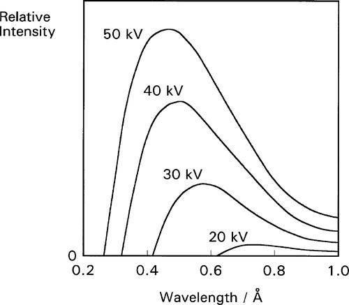
The continuous radiation spectrum produced in such a system is called ‘white’ in this field, simply because all wavelengths up to the limit are represented, ignoring the fact that the intensity is not uniform. It is this kind of radiation that is used for radiography. Typical curves of emission intensity vs. wavelength for several accelerating voltages are shown for a tungsten target in Fig. 2.2.[1] Note the sharpness of the short-wavelength limit, the shift of the peak intensity to shorter wavelength, and the increase in area beneath the curves (total intensity) with increasing voltage.
•2.3 Generation
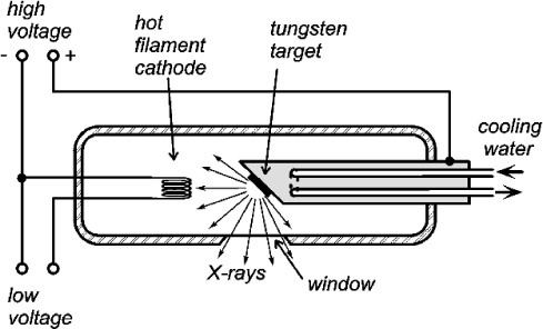
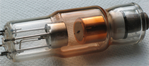
A schematic diagram of an X-ray tube of the so called Coolidge type3 is shown in Fig. 2.3, and an actual tube in Fig. 2.4. The envelope is borosilicate glass and holds a high vacuum. Electrons emitted from a resistively-heated filament (the cathode) are accelerated by a high voltage to strike a metal target, the anode. As the number of such thermionic electrons emitted by the cathode depends only on its temperature, the tube current (that flowing between the cathode and the anode, usually expressed in milliamps [mA]) is independent of the accelerating voltage. Thus the spectrum of the radiation emitted is itself independent of the tube current, which therefore only controls the total intensity (the ‘brightness’ of the source), a great operational advantage.
Experimentally, it has been found that for the ‘white’ radiation produced under these conditions both the total radiation produced and the intensity of the peak are approximately proportional to the atomic number (Z) of the target material. Thus, for good emission efficiency the target should be of a heavy metal, and tungsten (Z = 74) is usual. Emission spectra as obtained from a tungsten target are illustrated in Fig. 2.2. It should be realized that these spectra are essentially those of decelerated electrons, as there are no element-specific effects discernible. The total radiation produced (the area under the emission curve) is proportional to the square of the applied voltage, for a given tube current. This voltage should then be increased as far as possible for efficient high intensity radiation. The total radiation produced is also directly proportional to the tube current, i.e. the number of electrons making impact, as might be expected.
The production of X-rays is extremely inefficient. The best that can be managed is about 0.2% at 100 kV. Hence, for a (continuous) tube current of, say, 10 mA only 2 W of X-rays in total may be produced. However, nearly 1 kW of heat is being dumped into a target of only a few square millimetres. This means that high melting point metals – such as tungsten (m.p. 3422°C, the highest value of all elements) – are advantageous, if not essential. The target may reach a temperature as high as 2700°C and would glow white-hot (see Fig. 24§4.6). Large X-ray sets for high intensity or long exposures require cooling water to be pumped through the target, which is usually a plate of the chosen metal embedded in a massive copper base, for good heat conduction (Fig. 2.4). For even larger machines rotating anodes are used to increase the effective surface area of the target spot to many times the actual size. Even then, because the radiation will be emitted over a full sphere, some into the target itself and some into free space, the available power in the chosen output ‘beam’ direction will be a very small fraction of that actually produced. Note that there is no practical way that X-rays for diagnostic use can be usefully focused because there is no possible equivalent of the mirror and condenser lens of a spotlight. To control the irradiation of the subject only collimation by masks may be used to create a ‘beam’. That is, highly absorbing casing and shutters are used to limit the angular extent of the emerging radiation, typically only just to illuminate the subject.
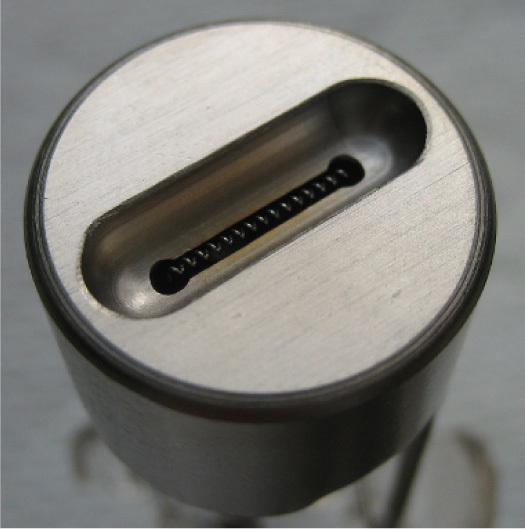
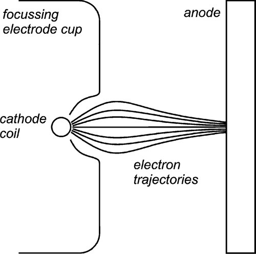
The intensity of the electron bombardment of the target means that to obtain sufficient output and avoid overheating, the area of the effective target must be large. However, a large target means that the image quality deteriorates by blurring (§8.3). The solution to this is a compromise: an elongated ‘line target’ placed at an angle to the intended beam direction, that is, at less than 90° to the electron beam axis. This allows the view of the target from the collimator to be foreshortened so that the source is apparently smaller, but the heat production is spread out. Obviously, the smaller the view angle (the target or bevel angle), the smaller the apparent source size in length (the width is unaffected). The angle cannot be zero because of internal absorption (§8.4). Normally, it may lie between about 10 and 20°. To achieve the necessary X-ray source shape, the cathode filament is an extended coil parallel to the beam direction, and lying in a U-shaped recess in the electrode (Fig. 2.5). The shape of this focussing cup modifies the electric field between the filament and the anode, guiding the electrons to the line focus (Fig. 2.6).
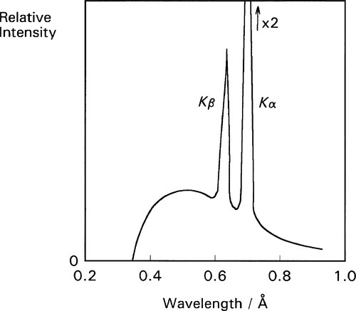
As the accelerating voltage applied to an X-ray tube is increased there comes a point when the energy of the electrons, corresponding to the short-wavelength limit (equation 2.3), is just sufficient to eject K-shell electrons from the target. For this and higher voltages, the characteristic X-rays for the refilling of those vacancies then appear in the emission spectrum for that target, superimposed on the ‘white’ radiation due to the impacting electrons’ deceleration. Fig. 2.7 shows this effect for a molybdenum target operated at 35 kV. In the case of tungsten the limit is 70 kV (hence the non-appearance of such peaks in Fig. 2.2). Of course, the same applies to L, M, N … excitation at progressively lower energies (if the atom possesses these levels filled), but for reasons seen later these are not of interest in the present context. The usual range for clinical diagnostic X-rays is 30 – 100 kV.
•2.4 Moseley’s Law
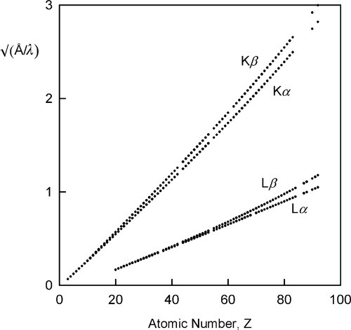
The variation in the energy of the characteristic X-rays was first studied by Moseley (one of Rutherford’s former students), who came to the conclusion that

where ν is the frequency of the radiation and Z is the atomic number of the element (and wavelength, of course, is inversely proportional to frequency) (Fig. 2.8). Although in fact this is only an approximation and not a strict relationship (the lines are curved), it is known as Moseley’s Law. It is an expression of the increasing stability of the inner shells as the atomic number increases (in fact, Moseley was responsible for developing the idea of atomic number[2]). This behaviour therefore further emphasizes the need for heavy metals to be used as targets if characteristic X-ray emission needs to be avoided. As will be seen later, relatively intense emission at long wavelengths would create a filtration problem because such radiation is not of diagnostic radiographic value, and a very thick filter that would appreciable attenuate the diagnostically useful radiation would be needed. If the characteristic radiation is at a useful energy, as for Mo (Fig. 2.7), or for W (at 69.5 keV), then it is only a matter of making appropriate allowance for the exposure (§5.1). Characteristic radiation can be as much as 10 to 30% of the total.
•2.5 Kinetic energy
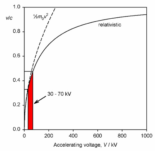
It should be noted that the energy statement represented by equation 2.1 is not accurately equivalent to that of the usual (Newtonian) kinetic energy equation, Ek = ½mv2, for the voltages relevant to dental diagnostic X-ray generation. This is because the electron velocity is an appreciable fraction of that of light in a vacuum, c, (which is an upper bound) and relativity must be invoked. The velocity is then given by:
where m0 is the rest mass of the electron. This function is plotted in Fig. 2.9, and compared with the Newtonian result. It can be seen that the errors becomes noticeable above about 30 kV, noting that the electron velocity at impact on the target is around 0.4 that of the speed of light, but lower than the simple calculation suggests.
§3 Lambert’s Law
The striking property of X-rays was, to Röntgen,1 their penetrating power. Indeed, it is this property that allows their use for imaging the internal structure of objects that are opaque to visible light. However, it is obvious that if they were too penetrating there would be no information conveyed in the emerging radiation. X-rays must undergo differential absorption (as with visible light, to create colour, 24§3.4) or differential scattering for there to be such information, that is variation between materials is necessary. The mechanisms of these processes will be dealt with in §4. For the moment only the macroscopic behaviour will be addressed. (For convenience we may discuss these processes as if they were due to absorption alone, for the moment, but it can be understood to include the effects of scattering as well: the result is the same in the line of the incident beam.)
X-radiation, like other electromagnetic radiation, has been found to obey Lambert’s Law. That is to say, the intensity decreases by the same fraction on passing through each successive, constant thickness layer of the medium, i.e. in differential terms, the rate of decrease of intensity in the beam is proportional to the intensity (more properly called the irradiance) I at that point:

where x is distance measured in the direction of the beam. In this equation the constant of proportionality, μ, is called the linear attenuation coefficient.4 The value of this coefficient is characteristic of both the substance and the wavelength of the radiation. Integrating equation 3.1 with respect to x gives the familiar form of the exponential decay function:

where x is the thickness of the object or layer5 and I0 is the intensity of the incident radiation (see 11§2.6); μ then has the units of cm–1.
The risk of interaction of an X-ray photon with an atom of a given element is a constant. It is independent of the chemical state of the atom because chemical reactions only involve outer, valence electrons, and the e.m.r. absorption of these does not lie in the X-ray region of the spectrum. Therefore, if a given number of atoms lie in the beam, it does not actually matter what the path length is, i.e. the distance over which they are spread.
Thus, if a given mass of vapour of, for example, bromine were contained in a long tube with a movable (X-ray transparent) end wall as a plunger to compress the gas, the measured absorption would be constant no matter where that end wall was placed. Nor, indeed, would it matter if the bromine were condensed as a uniform film of liquid on the end wall. Again, freezing it would make no difference. To measure the total amount of bromine present per unit area of cross section, irrespective of its distribution in the tube, we must take the product ρx, where ρ is (average) density over the length of the tube x. If this is inserted in equation 3.2 we must also make a corresponding adjustment to the coefficient to maintain the exponent as a dimensionless quantity, thus:
The term in parenthesis, μ/ρ, is called the mass absorption coefficient.6 It expresses the fact that it is the number of absorbing atoms that matters rather than the distance over which they are spread. For example, while diamond is extremely transparent to visible light, and graphite is completely opaque (because of its metallic nature, 11§1), both forms of carbon have exactly the same mass absorption coefficient for X-rays. Similarly, water has the same value for μ/ρ in the solid, liquid and gaseous states; the same value in fact as a mixture of H2 and O2 in the stoichiometric proportions of water, 2 : 1, or even a 1 : 1 mixture of H2 and H2O2.
It may be recognized that density is equivalent to concentration, since ρ/A = mol/mL (A = molar mass) and the mole is defined as a fixed number of entities, i.e. Avogadro’s Constant. If x is held constant, equation 3.3 is therefore effectively a version of Beer’s Law.[3] Taken together, equations 3.2 and 3.3 are sometimes known as the Beer-Lambert Law.
•3.1 Calculation
The last two examples above take the chemical independence of X-ray absorption of a given element a step further: that it is not affected by the other elements that are present. Alternatively, we can say that, in a given medium, the overall mass absorption is the sum of the mass absorptions for all elements present – simply additive. We have, of course, to take account of the relative amounts of the various elements over the complete path, so the summation is weighted by the mass fraction (M) for each of the n elements present, i.e. the overall mass absorption coefficient is given by:
where ∑ Mi = 1 in the usual way. Then, to obtain the linear absorption coefficient, μ, for the real material as a whole, we simply multiply by its observed overall density. We can therefore deal with any material no matter what its physical state or its arrangement in space, whether it is solid, a foam, a loose packed powder, or just a stack of plates with gaps.
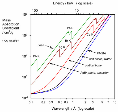
The use of μ/ρ follows the approach taken in other contexts where intensive properties of a material are preferred, such as modulus of elasticity: the effect of size or shape of the object has been eliminated. Thus, there are tables of mass absorption coefficient for many elements and X-ray wavelengths.[4] These can be used to calculate μ/ρ for any material in any condition. We may take PMMA as an example. Since it has an empirical formula somewhat similar to that of soft tissue overall, a consideration of its general behaviour is instructive.
Given the empirical formula: C5H9O2, and formula weight: 101.126, for PMMA, and for λ = 0.5609 Å (Ag-Kα radiation),[3] we have:
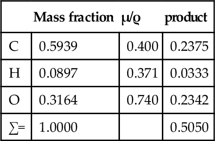
i.e. μ/ρ for PMMA is 0.505 cm2/g at that wavelength. Its density at room temperature is about 1.19 g/cm3, so that μ = 0.601 cm– 1. Similar calculations give values for μ/ρ for acrylic for a variety of wavelengths (Table 3.1, Fig. 3.1).
Table 3.1
Variation in mass absorption coefficient with wavelength for PMMA.
| λ/Å | (μ/ρ)/(cm2/g) |
| 0.5609 | 0.505 |
| 0.7107 | 0.820 |
| 1.5418 | 6.41 |
| 1.7902 | 9.87 |
| 1.9373 | 12.4 |
| 2.2909 | 20.2 |
•3.2 Filtration
Especially to be noted is the steady and rapid increase in μ/ρ with increasing wavelength, even though the elements concerned are very light. Soft tissue also shows this (Fig. 3.1), tending to absorb long wavelength radiation efficiently. This has two results:
2) since the absorption of radiation must result in ionization and free radical formation, damage to DNA, proteins, and other cell components must ensue from the reactions such ionization would initiate (§4.5).
Thus, for diagnostic purposes, filtration of the X-rays of the incident beam is essential. Aluminium is frequently chosen as a filter medium because it is both a light element – and so absorbs radiation appropriately (which means letting enough of the short wavelength radiation through to be useful) – and reasonably cheap. In addition, it is easily fabricated into any desired shape. The effectiveness of such a filter can be calculated by rewriting equation 3.2 as:
where T is the fraction of the radiation transmitted; this is known as the transmittance of the filter. The density of aluminium is about 2.70 g/cm3 and, using the values of μ/ρ given in the second column of Table 3.2, T can be calculated vs. λ. The long wavelength filtration is seen to be very efficient.
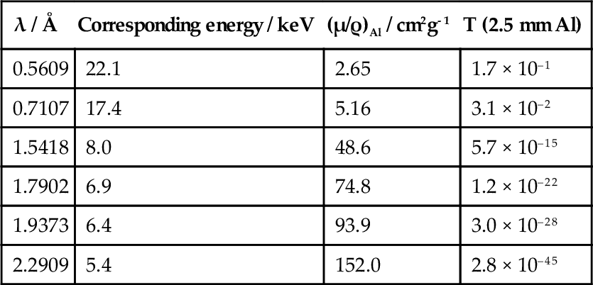
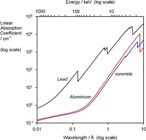
Similar calculations can be applied to determine the thickness of shielding required around X-ray generators, using such materials as lead and concrete. Although the latter is much less absorbent, indeed rather similar to aluminium (Fig. 3.2), it is much cheaper and so can be used in great thickness if necessary.
•3.3 Spectral effects
So far we have only discussed the behaviour of monochromatic radiation, whereas the output of an X-ray tube is ‘white’. Since the mass absorption coefficient is specific for each element at each wavelength, the total absorption would have to be calculated by reference to the incident spectrum, treating each wavelength independently and summing the results. While this is not in general a practical proposition, it does indicate some features of behaviour which should be recognized.
Firstly, in the context of radiation protection this means that successive increments of shielding are progressively less efficient. The long wavelength radiation may have been reduced to an insignificant intensity, but the short wavelengths – being more penetrating – require substantially more material to achieve similar reductions. The standard references take this into account. It suggests that it is protection against the most energetic X-rays (i.e. the highest voltage used in the generating tube) that is the dominating consideration.
Secondly, if an attempt is made to determine the linear absorption coefficient of a material by noting the intensity vs. thickness behaviour and using white radiation (even if filtered as for diagnostic use), the value may be seen to diminish with thickness. This is not a failure of Lambert’s Law but the result of the spectrum of the radiation changing as it travels through the material because of the differential absorption of the various wavelengths. In any case, one could only report the apparent linear absorption (attenuation) coefficient for that particular source and for the thickness of the material approaching zero (the limiting value), as a guide value rather than a true material property.
3.4 Rectification
It has already been pointed out that the X-ray spectrum depends on accelerating voltage (Fig. 2.2). But we have been discussing this as though the voltage was constant for any given exposure; it is not. To understand the implications of this it is necessary to examine how the accelerating voltage is generated.
In general, domestic mains electricity is commonly supplied at some 100 or 200 Vac, and at a frequency of 50 or 60 Hz (Fig. 3.1). Clearly, such a voltage is too low to be useful (equation 2.3) and must be stepped-up with a transformer, a pair of coils wound on a common magnetic circuit (typically of easily magnetizable – “magnetically soft” – iron). The effect of this is to raise the output voltage in proportion to the ratio of the number of turns in the primary and secondary windings of the transformer. The variation of the current in the primary coil induces a magnetic field, the variation of which induces a current in the secondary coil, but now 90° out of phase with that in the primary. The phase, of course, is of no consequence to the production of X-rays, but the alternating voltage is: only one half of each cycle would have the correct sense to generate an appropriate tube current (see Fig. 2.3), the other would be wasted as heat (Fig. 3.3, top). A system that behaves like this is called self-rectified, as the behaviour is intrinsic. Accordingly, the voltage must be rectified, that is, made to be of just one polarity. The device which achieves this is known as a rectifier. This is based on an electronic device called a diode, whose characterizing property is that it conducts electricity in one direction very much more easily than in the other. Thus, applying an alternating voltage to a diode results in transmission of the voltage on each half cycle (Fig. 3.3, second graph). This is then known as half-wave rectification, for the obvious reason. It is not very efficient in the sense that half the power expended is wasted as heat in the transformer. A full-wave rectifier makes full use of both halves of the cycle (Fig. 3.3, third graph) by using the ‘one-way valves’ of the diodes to good effect. More elaborate circuits may be used.
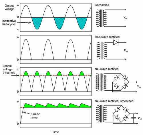
Even so, it is apparent that the voltage still varies from zero to the peak and back to zero in the course of each half-cycle. If we notice that radiation corresponding to less than some accelerating voltage is of no diagnostic value (say, 50 kV), and would in any case be largely filtered out (Table 3.2), there is still considerable inefficiency in that much of the cycle is still wasted. Even so, to reduce the patient’s unnecessary exposure, the filtration would have to be very heavy. This may be overcome by smoothing, the use of capacitors in the circuit such that the voltage is built up during each half-cycle, but then decays (exponentially) at a rate lower than the timescale of input voltage variation as current is drawn. The effect is to generate an output voltage waveform that ripples rather than oscillates over the full range (Fig. 3.3, bottom). By such a means, the voltage supplying the X-ray tube can be maintained above that which is minimally useful for diagnostic purposes. Modern equipment uses more efficient circuits: “switching” supplies which generate high frequency output – several kilohertz, and diode arrays called voltage doublers that can produce the necessary high voltage without a transformer. Rectification is still required, but the capacitors for smoothing can be much smaller, making the X-ray set much smaller and neater altogether.
None of this would be of any particular concern in dentistry were it not for one thing: the emitted X-ray spectrum depends on voltage (Fig. 2.2). Thus, during the course of a half-cycle, whether in a half- or full-wave (unsmoothed) circuit, the spectrum must vary dramatically. Such variation is considerably reduced by smoothing, and obviously the better the smoothing the better the constancy, and the closer will be the radiation spectrum to that suggested by the peak voltage (Fig. 2.2). Obviously, at the start of the exposure the voltage must rise from zero in the ‘turn-on ramp’, and likewise return at the end. Although the amount of non-useful radiation produced this way is small, as a proportion of the total in very short exposures (0.05 s or less, 2 or 3 a.c. cycles) it is reduced to insignificance in high-speed switching power supplies because the time spent in that region is very small.
It follows then that the effective irradiation spectrum (the time-weighted average) for patient and film is a function of type of rectification and smoothing as well as peak voltage and filtration. This means that because overall attenuation depends on spectrum, diagnostic images must vary somewhat according to the actual X-ray set in use, and not just the obvious settings of the accelerating voltage, milliamperage and exposure time.
§4 Absorption and Scattering
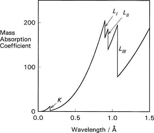
It is apparent from the above that the atomic number (Z) of the element and the wavelength of the radiation (λ) are both important in determining the value of μ/ρ. But a detailed plot of μ/ρ vs. λ is revealing in another sense. Using platinum as an example (Fig. 4.1) we find that the curve is by no means smooth but rather shows discrete, abrupt and large discontinuities. These are known as absorption edges. They are due to the absorption to be expected when the energy of the radiation is just equal to that required to remove one of the electrons (i.e. just large enough, reading the wavelength scale from right to left), and they are labelled according to the electron transition process involved. Absorption edges correspond to the critical absorption wavelengths mentioned earlier (§1).
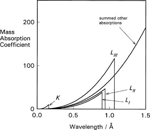
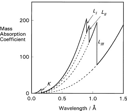
For each of these separate types of electronic transition, as the energy increases (λ decreases) so the efficiency of the interaction of electron and radiation decreases. Each such process is independent of the others so, dissecting out the separate absorption curves, we obtain a figure such as Fig. 4.2. The overall effect at any wavelength is therefore seen to be a summation of all possible absorptions (Fig. 4.3).
If ejection of the electron does occur the energy in excess of that required just to remove the electron will appear as its kinetic energy. The energies of these absorption edges therefore correspond to the excitation transitions of Fig. 1.1. What happens next is of clinical importance. Fast electrons are capable of initiating chemical reactions as a result of many interactions with outer (bonding) electrons, the collisions imparting some energy to the other electrons such that they are ejected from their molecular orbitals. This is why X-rays are described as ionizing radiation. The absorption of radiation that does occur is thus made more effective (and therefore damaging) in this sense than a one electron per photon calculation would indicate.
The actual chemistry of the formation of the image in a photographic or radiographic film ‘emulsion’7 is a complex matter that need not be discussed here; however, one feature can be noted. There are absorption edges for silver and bromine, i.e. the constituents of the sensitive silver bromide crystals in the emulsion of the radiographic film, at 0.486 and 0.920 Å respectively. This leads to intense absorptions of radiation by these elements at those, and shorter, wavelengths. Such radiation is therefore rather more effective in producing a latent image in the emulsion than visible light, which can only affect the outermost electrons. The effect can be demonstrated by using a crystal as a diffraction grating to obtain a spectrum, much like visible light may be diffracted. It should be noted that radiation is indeed present but simply passing through the film, at energies corresponding to the gaps between the L-series lines (see Fig. 1.1). The image is lacking because the absorption by the film is very weak. However, in practice, the radiation corresponding to the region of the L-series characteristic X-rays of W would be heavily absorbed by an Al-filter and would not contribute to an ordinary clinical radiographic image.
•4.1 Scattering
Absorption has been discussed as if there were only the one process operating, as indicated at the beginning of §3. There are in fact two separate components to the reduction of transmitted beam intensity. True absorption is due to the transformation of X-rays into the kinetic energy of electrons, having first promoted them to the ‘free’ state as discussed above. These ejected electrons leave vacancies into which other electrons may cascade (§1), thereby producing fluorescent radiation which will be emitted in all directions. As with other fluorescence processes (6§5.2, 24§4.9, 24§6.5), the wavelength of such secondary characteristic radiation cannot be shorter than the original absorbed radiation. It is therefore capable of being subsequently absorbed quite efficiently, and therefore adding to the damaging action of the primary beam, but over a larger volume.
Scatter, however, is due to a transfer of energy from the incident beam to secondary rays through interaction with the atoms of the medium, but not mediated by electronic transitions. The observed overall mass ‘absorption’ or attenuation coefficient can thus be separated into two components:

for true absorption (τ/ρ) and scattering (σ/ρ). This scattering coefficient is nearly constant, varying little with either λ or Z. But scatter is itself due to two entirely separate processes. (Electron-positron (e–, e+) pair production can be ignored for dentistry because the accelerating voltage used is generally not high enough, i.e. < ~ 1 MV, since 2 × 0.511 MeV, the rest mass-energy of each particle, is required for this.)
•4.2 Compton effect
Electromagnetic radiation imposes, as its name implies, oscillating electric and magnetic fields on the matter on which it impinges. Electrons, being charged, will then tend to oscillate in such fields. But an oscillator must itself re-radiate energy, so that the net effect is for energy to be removed from the incident beam and reradiated in random directions. The radiation that is not scattered, continuing on in the beam, must then have a slightly longer wavelength, corresponding to its reduction in energy. This process only applies to free or loosely bound electrons such as in the outermost, bonding, shells where the available energy levels are very close together. Their occurrence is therefore essentially constant despite changes in Z. However, these electrons are relatively more important at low Z, as the proportion of the total number of electrons present. This scattering process is called the Compton effect.
•4.3 Coherent scattering
The second scattering process is due to the fact that the separations between atoms (centre to centre) are of about the same scale as the wavelengths of X-rays. There are therefore reflection and interference phenomena associated with this condition. As far as the determination of crystal structures is concerned, this coherent scattering from well-organized layers of atoms as in crystals, otherwise known as diffraction, has been overwhelmingly important to our understanding of the structure of matter through X-ray diffraction analysis. However, the general irregularity (non-crystallinity) and complexity of matter, and especially soft tissue, as well as its thermal motion, results in a general ‘background’ of scattered radiation of exactly the same wavelength as the incident beam. That is, there is no absorption and reradiation of energy, and it may be viewed as ‘pure’ lossless scatter. For practical structure determination by diffraction a monochromatic X-ray source is ideal. With the polychromatic or ‘white’ continuum of radiographic X-rays the superimposition of all possible diffraction peaks, even from an obviously well-crystalline material such as hydroxyapatite, results in no structural information being decipherable.
The existence of coherent scattering means that a slight adjustment must be made to the thinking about attenuation coefficients as expressed by equation 4.1. Clearly, the crystallographic form affects the amount of scattering (the type of crystal symmetry and angular orientation of the crystal planes to the beam direction), but also the atoms involved (Z), the temperature (as it affects lattice spacing) and ionic charges are involved (Z in effect referring to the electron count, the nuclear charge having no relevance8). Thus, although crystallinity has an effect, it is physical rather than chemical in origin. Even so, for biological systems the magnitude of the effect is small and can be ignored.
These two scattering processes add further to the non-primary beam radiation to which the surroundings of the deliberately irradiated area are subject. This accounts, in part at least, for the use of ‘lead’ aprons and thyroid shields. It is also the reason for the lead foil included in radiographic film packets.
Although both Ag and Br have moderately high atomic number, Z, and the corresponding mass absorption coefficients are high, the rather small amount of AgBr present in the emulsion (of the order of a few mg/cm2) does not absorb more than a few percent of the incident beam. The radiation which penetrates will continue on to the film packet or cassette and, in the case of intraoral films, to tissue on the other side of the mouth. This transmitted radiation will produce secondary scattered radiation by interacting with that tissue or other materials. Since this radiation is emitted or scattered in all directions, some would come back to the film. This would also interact with the film emulsion and tend to ‘fog’ the diagnostic image (there can be no image information in that backscattered radiation). (There is also some scattering in the forward direction from all material in front of the film and this adds to the fog. This becomes significant for deep bod/>
Stay updated, free dental videos. Join our Telegram channel
VIDEdental - Online dental courses


