Chapter 25 Clinical Biomechanics in Implant Dentistry
The discipline of biomedical engineering, which applies engineering principles to living systems, has unfolded a new era in diagnosis, treatment planning, and rehabilitation in patient care. One aspect of this field, biomechanics, concerns the response of biological tissues to applied loads. Biomechanics uses the tools and methods of applied engineering mechanics to search for structure-function relationships in living materials.1 Advancements in prosthetic, implant, and instrumentation design have been realized because of mechanical design optimization theory and practice.2 This chapter provides fundamental concepts and principles of dental biomechanics as they relate to long-term success of dental implants and restorative procedures.
MASS, FORCE, AND WEIGHT
Mass, a property of matter, is the degree of gravitational attraction the body of matter experiences. As an example, consider two cubes composed of hydroxyapatite (HA) and commercially pure titanium, respectively. If the two cubes are restrained by identical springs, then each spring will deflect by a certain amount relative to the attraction of gravity for the two cubes. The two spring deflections in this example can be made equal by removing part of the material from the titanium cube. Even though the cubes are of completely different composition and size, they can be made equivalent with respect to their response to the pull of gravity. This innate property of each cube that is related to the amount of matter in physical objects is referred to as mass. The unit of mass in the metric (International System of Units) system is the kilogram (kg); in the English system, it is the pound mass (lbm).3
In 1687, Sir Isaac Newton described a force in what is now referred to as Newton’s laws of motion.3 In his second law, Newton stated that the acceleration of a body is inversely proportional to its mass and directly proportional to the force that caused the acceleration. The familiar relation expresses this law:

where F is force (newtons [N]), m is mass (kilograms), and a is acceleration (meters per second squared [m/sec2]). In the dental implant literature, force commonly is expressed as kilograms of force. The gravitational constant (a = 9.8 m/sec2) is approximately the same at every location on Earth; therefore mass (kilograms) is the determining factor in establishing the magnitude of a static load.
Weight is simply a term for the gravitational force acting on an object at a specified location. Weight and force can be expressed by the same units, newtons or pound force (lbf). If a titanium cube is considered as though placed on the moon, then its weight (force caused by gravity) is different from its weight on the Earth. The mass in the cube has not changed, but the acceleration caused by gravity has changed. Recalling Sir Isaac Newton’s work, an apple weighs approximately 1 N (0.225 lbf). The reader will find the conversion factors in Box 25-1 useful.4
FORCES
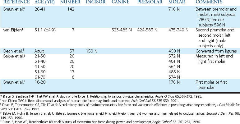
Forces may be described by magnitude, duration, direction, type, and magnification factors. Forces acting on dental implants are referred to as vector quantities; that is, they possess magnitude and direction. Restated, to state simply that “a force of 75 lb exists on the distal abutment” is not sufficient. The more correct statement is “a force of 75 lb exists on the distal abutment directed axially along the long axis of the implant body.” The dramatic influence of load direction on implant longevity and bone maintenance is discussed later in this chapter and others. Typical maximum bite force magnitudes exhibited by adults are affected by age, sex, degree of edentulism, bite location, and especially parafunction5–9 (Table 25-1).
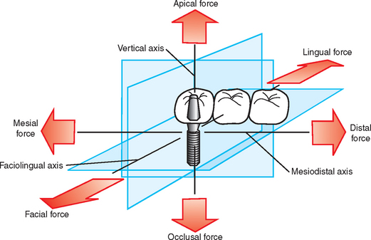
A force applied to a dental implant rarely is directed absolutely longitudinally along a single axis. In fact, three dominant clinical loading axes exist in implant dentistry: (1) mesiodistal, (2) faciolingual, and (3) occlusoapical (Figure 25-1). A single occlusal contact most commonly results in a three-dimensional occlusal force. Importantly, this three-dimensional force may be described in terms of its component parts (fractions) of the total force that are directed along the other axes. For example, if an occlusal scheme on an implant restoration is used that results in a large magnitude of force component directed along the faciolingual axis (lateral loading), then the implant is at extreme risk for fatigue failure (described later in this chapter). The process by which three-dimensional forces are broken down into their component parts is referred to as vector resolution and may be used routinely in clinical practice for enhanced implant longevity.
Three Types of Forces
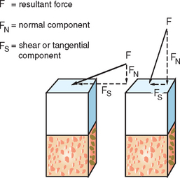
Forces may be described as compressive, tensile, or shear. Compressive forces attempt to push masses toward each other. Tensile forces pull objects apart. Shear forces on implants cause sliding. Compressive forces tend to maintain the integrity of a bone-implant interface, whereas tensile and shear forces tend to distract or disrupt such an interface. Shear forces are most destructive to implants and bone compared with other load modalities. In general, compressive forces are accommodated best by the complete implant-prosthesis system. Cortical bone is strongest in compression and weakest in shear10 (Table 25-2). Additionally, cements and retention screws, implant components, and bone-implant interfaces all accommodate greater compressive forces than tensile or shear. For example, whereas the compressive strength of an average zinc-phosphate dental cement is 83 to 103 MPa (12,000 to 15,000 psi), the resistance to tension and shear is significantly less (500 psi) (Figure 25-2).
| TYPE OF FORCE APPLIED | STRENGTH (MPa)* | LOAD DIRECTION/COMMENTS |
|---|---|---|
| Compressive | 193.0 (13.9) | Longitudinal |
| 173.0 (13.8) | 30 degrees off axis | |
| 133.0 (15.0) | 60 degrees off axis | |
| 133.0 (10.0) | Transverse | |
| Tensile | 133.0 (11.7) | Longitudinal |
| 100.0 (8.6) | 30 degrees off axis | |
| 60.5 (4.8) | 60 degrees off axis | |
| 51.0 (4.4) | Transverse | |
| Shear | 68.0 (3.7) | Torsion |
* Standard deviations are listed in parentheses.
From Reilly DT, Burstein AH: The elastic and ultimate properties of compact bone tissue, J Biomech 8:393, 1975.
The implant body design transmits the occlusal load to the bone. Threaded or finned dental implants impart a combination of all three force types at the interface under the action of a single occlusal load. This “conversion” of a single force into three different types of forces is controlled completely by the implant geometry. The prevalence of potentially dangerous tensile and shear forces in threaded or finned implants may be controlled optimally through careful engineering design. Cylinder implants in particular are at highest risk for harmful shear loads at the implanttissue interface under an occlusal load directed along the long axis of the implant body. As a consequence, cylinder implants require a coating to manage the shear stress at the interface through a more uniform bone attachment along the implant length. Bone loss adjacent to cylindrical implants and coating degradation result in a mechanically compromised implant.
Stress

where σ is stress (pounds per square inch; pascals), F is force (newtons; pound force), and A is area (square inches; square meters). The internal stresses that develop in an implant system and surrounding biological tissues under an imposed load may have a significant influence on the long-term longevity of the implants in vivo. As a general rule, a goal of treatment planning should be to minimize and evenly distribute mechanical stress in the implant system and the contiguous bone.
The magnitude of stress depends on two variables: (1) force magnitude and (2) cross-sectional area over which the force is dissipated. It is rare that a dentist can control the force magnitude completely. The magnitude of the force may be decreased by reducing these significant magnifiers of force: cantilever length, offset loads, and crown height. Night guards to decrease nocturnal parafunction; occlusal materials that decrease impact force; and overdentures, rather than fixed prostheses, that can be removed at night are further examples of force reduction strategies. The functional surface area over which the force is distributed, however, is controlled completely through careful treatment planning.
Stay updated, free dental videos. Join our Telegram channel
VIDEdental - Online dental courses


