Chapter 2
Radiographic Imaging in Oral and Maxillofacial Surgery
Introduction
The most common radiographic examinations of oral and maxillofacial surgery patients are intraoral and panoramic radiographs. However, today computed tomography (CT) and magnetic resonance imaging (MRI) are common examinations in imaging of many different conditions. A useful investigation is one in which the result – positive or negative – will alter management or add confidence to the clinician’s diagnosis. It is important to try to minimize the radiation dose to the patient (particularly children). CT can potentially give significant absorbed doses to the patient. The trend today is to use a low-dose technique for CT, but this can be at the expense of the image quality and its use depends on the clinical problem.
Computed Tomography (CT)
CT is a digital technique providing images of thin slices of the patient with a variable thickness. The slice thickness can be less than 1 mm by use of very small X-ray detectors and a fan-shaped X-ray beam transmitted through the patient. By simultaneously scanning several slices of the body (multislice CT), the scan time can be reduced significantly and the smallest details can be imaged within short scan times. Multislice CT enables a wide range of clinical applications and, through the use of computer software, three-dimensional (3D) images can be produced. Images can be viewed in the axial, coronal, or sagittal planes depending on the diagnostic task. This is referred to as multiplanar reformatted (MPR) imaging. Images can also be viewed in any other plane decided by the operator. CT has the advantage over other radiographic techniques that it eliminates superimposition of images of structures outside the area of interest. It has an inherent high-contrast resolution and differences between tissues that differ in physical density by less than 1% can be distinguished. For image display, each pixel is assigned a CT number (Hounsfield units – HU) representing density. The density of air is defined as −1000 HU, water as 0 HU and bone tissue has more than +400 HU. To allow the observer to interpret the image, only a limited number of HU are displayed. A clinically useful gray scale is achieved by setting the window level and window width on the computer console to a suitable range of HU, depending on the tissue being studied. The term “window level” represents the central HU of all the numbers within the window width. The window width covers the HU of all the tissues of interest and these are displayed as various shades of gray.
Cone-Beam Computed Tomography (Cone-Beam CT)
This technique has been commercially available since the early years of the present century. Cone-beam CT is based on volumetric tomography, in contrast to conventional fan-beam CT where slices are scanned. From this, volume slices can be reconstructed in various planes. One advantage with cone-beam CT compared to conventional CT is the lower radiation dose. The radiation dose is reduced by up to 98% compared with conventional CT and is comparable to 2–28 average panoramic radiographs. The dose varies substantially, however, depending on the device, imaging field and selected technique factors. The scan time is relatively short (around 10 s) and the resolution is high (i.e. around 0.125 mm) and approaches that of fan-beam CT. The software is usually adapted to maxillofacial imaging and is real-time interactive, for example for implant planning.
In both cone-beam CT and conventional CT, artifacts are produced by metal objects and it is important to try to avoid exposing metal fillings and crowns.
Magnetic Resonance Imaging (MRI)
MRI does not use ionizing radiation, but rather uses magnetic fields to align protons in the body, which can then be recorded electronically as they revert to their baseline orientation, and reformatted to build up an image. There are, however, some contraindications since the presence of ferromagnetic metals is a potential hazard. Patients with magnetic or para-magnetic metallic foreign objects, pacemakers, and metal clips must not be examined. Pregnancy is a relative contraindication.
The advantage of MRI is that it offers the best resolution of tissues of low inherent contrast and it has an excellent soft tissue contrast resolution. Disadvantages are relatively long imaging times and patients who suffer from claustrophobia cannot be examined. Open MRI scanners are sometimes used for claustrophobic patients but the images are of low resolution and are usually unsuitable for head and neck imaging.
MRI physics is complex and an understanding of the basic concepts is important in order to manipulate the scan parameters to improve the quality of the images.
Impacted Teeth
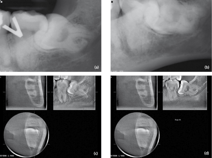
A preoperative examination of an impacted tooth usually consists of two intraoral radiographs exposed at different angles (Fig. 2.1 a and b) or a panoramic radiograph. Using intraoral films in three different projections gives an insight into the true anatomy of third molars when the radiographic appearance was compared to the clinical observation. Intraoral and panoramic radiographs are usually sufficient to show the relationship between the roots of the third molar and the mandibular canal. However, narrowing of the canal, increased radiolucency (“dark band”) and interruption of the radiopaque border of the mandibular canal can justify a CT examination. Cone-beam CT has been shown to have a high diagnostic accuracy in predicting neurovascular bundle exposure during extraction of impacted mandibular third molars. Figure 2.1 c and d show an example of an impacted mandibular third molar with a complicated root anatomy examined with cone-beam CT.
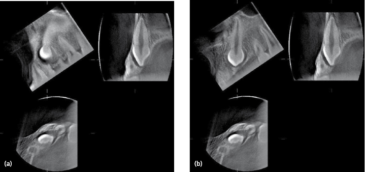
CT is also valuable when examining impacted teeth in other regions. Cone-beam CT has been shown to be indicated for localization of impacted maxillary canines and has demonstrated root resorption better on the adjacent incisors compared to conventional radiography. Figure 2.2 shows a cone-beam CT examination of a non-erupted maxillary canine causing resorption of the root of the lateral incisor.
Pathological Conditions – Inflammatory Lesions, Cysts, Benign and Malignant Tumors
The aims of the radiographic examination are to give information that leads to the most probable diagnosis and to the optimal treatment. The examination must cover />
Stay updated, free dental videos. Join our Telegram channel
VIDEdental - Online dental courses


