Chapter 16
Implant Placement in the Posterior Mandible
Anatomy of the Posterior Edentulous Mandible
Normal Topography
The curvature of the alveolar process of the mandible is narrower than the body itself; the posterior parts of the alveolar process are positioned much more lingually than the mandibular body. In the second and third molar area the bony substance of the oblique line, running from the coronoid process, is superimposed on the outer alveolar plate because of this divergence of the alveolar process and mandibular body. This gives an impression of a thick alveolar plate. Lingually, the temporal crest from the medial part of the coronoid process follows the course of the oblique line. Behind the third molar these two lines form the retromolar triangle which continues anteriorly as the alveolar crest. To accommodate the comparatively thicker roots of the molars the alveolar crest is wider and the crest flatter in the posterior than in the anterior parts of the mandible. Lingual to the second and third molars the downwards sloping mylohyoid line adds to the thickness of the superior parts of the alveolar crest. Hence, a cross-section of this part of the mandible is angulated lingually.
In the first and second molar area there is a shallow concavity in the lingual surface, the submandibular fossa. Further anteriorly, in the area corresponding to the premolars, the more distinct sublingual fossa is found.
As the oblique line continues anteriorly and inferiorly it gets less pronounced which gives the impression of a thinner mandible. The orifice of the mental canal, the mental foramen, is found in the buccal cortex, between the roots of the first and second premolar, usually a couple of millimeters below the apices. As the curvature of the mandible increases in this region, the anterior rim of the orifice is sharper than the posterior.
The Mandibular Canal
The mandibular neurovascular bundle enters the mandibular canal through the mandibular foramen. This is a wide opening situated approximately in the center of the lingual surface of the mandibular ramus, hidden behind a thin, bony process, the lingula. During the first 8–10 mm the canal runs close to the lingual cortex. As it descends it moves to a more central position in the bone in a smooth curve downward and forward into the mandibular body some 6–8 mm from the mandibular base. The curvature of the canal is less pronounced as it continues in the mandibular body. This means that the canal runs continuously closer to the mandibular base until it reaches the area between the first and second molar from where it moves upwards to the mental foramen in an increasingly sharp curve. As the canal moves inferiorly it moves lingually and reaches its most lingual position at its most inferior position, between the first and second molar. From there it runs closer to the buccal cortex. When the mandibular canal forks into an incisor canal, containing the anterior plexus of the nerve, and a mental canal (usually called the mental foramen), containing the mental nerve, the canal is positioned approximately 3–4 mm from the buccal surface. What is known as the mental foramen is actually a canal through which the first 2–4 mm of the mental branch of the mandibular nerve run before it leaves the mandibular body apical to, and between, the first and second premolar. However, in a few cases its location may vary from the canine to the first molar. The mental canal usually runs perpendicular to the sagittal cardinal axis of the head. Thus it runs slightly posteriorly to the surface of the mandible after leaving the mandibular canal but the pattern of emergence seems to vary between population groups. The posterior direction may be readily seen in lateral radiographs and has been interpreted as a loop. The length of the loop has been measured at between 0 and 7.5 mm. However, others have shown that the loop is a radiographic artifact rather than an anatomic structure and that it should have no impact on implant surgery. The anterior and posterior walls of the mental canal are frequently not parallel, but converge towards the foramen, which may explain the difference in findings between radiographs and clinical findings.
As the upwards curve of the mandibular canal is accentuated close to its ramification, the mental canal reaches the mental foramen slightly from below. The incisor canal continues anteriorly after the furcation of the nerve. The size of the canal anterior to the furcation varies considerably; from being the same size as the main canal to a diminutive, almost invisible canal. However, even in cases where the canal is initially rather wide it soon narrows as it runs anteriorly.
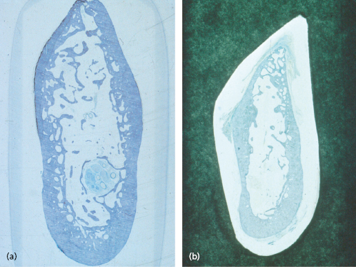
The expression “mandibular canal” may give a false impression of a rather robust structure with thick cortical walls. In a few cases this may be true (Fig. 16.1a) but in most cases the walls are fairly thin, in some cases they seem almost non-existent (Fig. 16.1b). Normally the walls of the mandibular canal are perforated by small vessels and nerve fibers leaving the neurovascular bundle to the teeth. It is not known whether these perforations eventually disappear when the vessels and nerve fibers atrophy after teeth have been extracted. The mental canal seems to be usually surrounded by solid cortical walls, which are a continuation of the buccal cortex.

The periosteum that covers the exterior surface of the mandible continues into the mental canal and along the mandibular canal as an endosteum covering the surface of the walls of the canals.
Resorption Patterns of the Alveolar Ridge
As the alveolar crest is wider in the premolar and molar area than in the anterior region, vertical resorption is slower in the posterior parts. On the other hand, molars and premolars are usually lost earlier than incisors. Thus when patients seek implant placement, the posterior regions are usually equally or more resorbed than the anterior.
In the posterior molar area resorption usually results in a wider arch and a wider crest as resorption reaches the oblique and mylohyoid lines. In the first molar and especially in the premolar area, two different resorption patterns are seen, although combinations of the two are common. Whether the resorption mode is due to the angulation of the alveolar crest or genetically determined is not known.
The usual pattern is vertical resorption. This results in a flat and rather wide crest. If the resorption is moderate, leaving more than 10 mm height of bone superior to the mandibular canal, implant placement is usually uncomplicated. However, as resorption continues, the height above the mandibular canal is reduced and in advanced cases, where resorption reaches the level of the mandibular canal, the foramen is found on the top of and even slightly lingual to the top of the crest with part of the alveolar nerve positioned under a thin layer of bone or even directly under the alveolar mucosa.
The other, less frequent, resorption pattern is lateral resorption. This results in a narrow crest, in advanced cases in a very high, thin ridge made up of cortical bone which is totally unsuitable for implant placement.
Implant Placement Superior to the Mandibular Canal
Conventional implant placement in the posterior mandible may be associated with the risk of nerve damage. However, as long as the distance between the superior cortex and the mandibular canal is 13 mm or more, implant placement in the posterior mandible is little different from elsewhere if the difficulties mentioned in the preceding section are observed. The distance between the surface of the alveolar crest and the roof of the mandibular canal can relatively accurately be calculated by means of a panoramic radiograph once the position of the mental foramen has been clinically established. When the distance is less, more accurate measurement becomes imperative. Numerous methods to establish the location of the mandibular canal have been presented. When extreme accuracy is needed, a surgical guide based on a three-dimensional (3D) model should be made and used during surgery.
Nerve damage may occur even if the canal is not directly traumatized during implant surgery. The implant seat is usually drilled 0.5–1 mm deeper than the length of the corresponding implant. When working close to the canal it is tempting to be cautious and drill less deep. This may result in the implant being placed a little deeper than the seat allows, compressing the apical cancellous bone, and, indirectly, the roof of the canal, without the surgeon realizing. This results in pressure on the neurovascular bundle. If the compression is minor, only a part of the sensory area may lose sensation temporarily. A more severe compression may lead to compartment syndrome in the nerve and permanent nerve damage with anesthesia, paresthesia or hyperesthesia. Should the surgeon observe any such symptoms postoperatively, the pressure on the nerve should immediately be eliminated, either by unwinding the implant one or two rounds or by open exploration of the nerve.
The Use of Wider Implants
To compensate for the reduced bone–implant contact area when shorter implants are used, wider implants may be considered. These also have an esthetic advantage in the posterior area; the wider neck of these implants mimics the size of the cervix of the molars. Both the esthetic and functional results may therefore be enhanced.
When using wider implants the surgeon should be aware that with increased diameter the speed at the periphery of the drill and implant are exponentially increased. Gentle drilling and placement of the implant are imperative to avoid failures due to overheating of the bone.
Placement of Implants Lingual to the Neurovascular Bundle
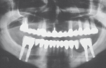
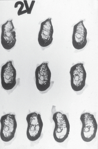
To allow the use of longer implants, placement lingual to the mandibular canal has sometimes been recommended. The impression that the implants are placed lingual to the neurovascular bundle and secured into the cortex at the base of the mandible may be given by illustrations such as Figure 16.2. However, as can be seen in Figure 16.3, the bone lingual to the mandibular canal is too thin to allow insertion of implants. To obtain a result as shown in Figure 16.2 the implants have to be angulated to perforate the lingual cortex immediately above or at the level of the canal and the implants are thus inserted into the floor of the mouth. This may have the advantage of double cortical anchorage but the method is highly dangerous and may even be life-threatening; fatal incidents have been reported after accidental perforations into the floor of the mouth. Due to the resilient tissues in the floor of the mouth, bleeding may pass unnoticed until it suddenly manifests itself as an airway obstruction. As the implant seat is drilled without visible or easily calculated reference points, laceration of the neurovascular bundle is also highly probable.


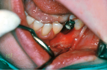
Of course, it may be argued that this technique allows for a bicortical anchorage of the implant, and in a few selected situations this technique may have its place. However, if the distance to the mandibular canal is short, the implants have to be angulated in a way that makes it difficult to achieve a satisfactory esthetic and functional prosthetic reconstruction (Fig. 16.4); in cases where the height above the canal is sufficient, a safer choice would be to choose to place a shorter and maybe wider implant above the canal rather than taking the risk of placing it lingual to the nerve bundle.

Crestal Split
Sometimes an advanced lateral resorption pattern of the alveolar crest results in a high but very narrow crest unsuitable for implant placement, even if implant perforations both lingually and buccally are accepted. In such cases, the intermaxillary space permitting, a so-called crestal split may be considered. Typically the method is used in the anterior maxilla but it can be adopted for use in the posterior mandible as well. The crest has to have a wide base containing cancellous bone that runs well into the top of the crest and the cortex must not be too thick. In these cases success rates in the range 85–95% have been reported. However, in the posterior mandible very few cases qualify for this procedure. The bone has to be elastic to permit bending or a controlled breaking. Thus the patient has to be young. In most cases the thin crest is made up of a unified lingual and buccal cortex without any cancellous bone in between. This makes a split highly unpredictable or even impossible. In most cases other methods are to be preferred.
Surgical Technique
After an incision has been made along the top of the crest, a lingually based flap is raised (Fig. 16.5). A buccal flap only about 2 mm wide is raised, to preserve the blood supply to the buccal cortical plate. A thin groove is drilled along the top of the crest until cancellous bone is reached. A chisel is cautiously driven well into the groove by a mallet while care is taken not to interfere with the neurovascular bundle. The chisel is then gently rotat/>
Stay updated, free dental videos. Join our Telegram channel

VIDEdental - Online dental courses


