Chapter 1
Basic Principles
Aim
The aims of this foundation chapter are threefold: first, to give an understanding of the nature of the radiographic image and the factors that govern its formation; second, to recognise the limitations of radiographs; finally, to describe a systematic approach to image interpretation.
Introduction
Our eyes constantly expose our brain to “images”. Our binocular vision allows us to cope with three-dimensions while our colour vision helps to characterise the subtle variations of the objects around us. In contrast, radiographs seem to present a far simpler view on things: x-ray images are two-dimensional and consist of black, white and shades of grey. Interpretation of radiographic images, however, poses very different challenges from those presented by everyday vision. An understanding of these is essential to interpretation.
What Makes the Image?
Image formation begins with a pattern of x-rays hitting the image receptor (film, intensifying screen/film combination or digital receptor). This pattern is recorded, either chemically (film) or electronically (digital radiography), and displayed as a pattern of densities. The image you see is dictated principally by three factors:
-
the nature of the radiation
-
the nature of the objects lying between the x-ray source and the receptor
-
the characteristics of the image receptor.
The Nature of the Radiation
X-ray energy and intensity are the important factors here.
X-ray energy
X-rays are high-energy, high frequency, short wavelength electromagnetic radiation. However, “x-rays” cover a band within the electromagnetic spectrum ranging from lower energy (lower frequency, longer wavelength) to higher energy (higher frequency, shorter wavelength). How the radiation that comes out of your x-ray set fits into this range of energies depends principally upon the kilo Voltage (kV). Most modern dental x-ray sets in the UK are in the 65 to 70kV band. Previously, many sets were manufactured to operate at 50kV. While the kV affects radiation dose, in this chapter we are concerned with the radiographic image. In this context, lower kV leads to high-contrast “black and white” images with few intermediate grey tones. Relatively higher kV produces images with more subtle variation in grey tones (longer grey scale) and lower overall contrast (Fig 1-1).
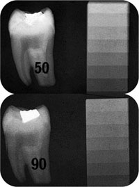
Fig 1-1 These images of a tooth and a small aluminium step wedge were produced at 50kV (top) and 90kV (bottom). The difference is subtle but the 50kV image shows greater contrast, seen most easily on the stepwedge.
X-ray intensity
The greater the intensity of x-rays the more radiation hits the film. This produces a higher-density (“darker”) image.
The Nature of the Object
The factors included in the “nature” of the objects are as follows.
Atomic number
This refers to the size of the atoms. High atomic number elements absorb x-radiation very effectively (Fig 1-2). Thus, materials like gold (atomic number = 79) absorb more radiation than calcium (atomic number = 20). High atomic number elements like barium (atomic number = 56) are added to some dental materials to make them radiopaque and thus help in making them visible on radiographs. In fact, the absorption of x-rays is proportional to the cube of the atomic number (“Z3 effect”), making this an extremely potent influence on overall x-ray attenuation by materials.
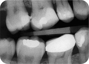
Fig 1-2 The most striking example of the effect of atomic number upon x-ray absorption is seen with an everyday radiograph. This bitewing shows the enormous contrast difference between metallic restorations (high atomic number) and everything else. The gold crown is very radiopaque because of its very high atomic number, while the composite restorations in a number of teeth are comparatively radiolucent. The bone and teeth (moderately high atomic number elements) are, in turn, substantially more radiopaque than areas showing soft tissues (low atomic number elements).
Physical density
Atomic size is not the only factor of importance in x-ray attenuation. Physical density also plays a significant role. The most practical example of this is the contrast between air and soft tissues. While the mean atomic numbers of these are quite small, the relatively low density of air means that there is a very obvious contrast on radiographs at air/soft tissue boundaries (Fig 1-3).
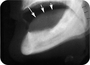
Fig 1-3 Air/soft tissue interfaces. Despite the fairly small difference in average atomic number between soft tissues and air, a visible contrast is present due to the large difference in density. The tongue outline is shown by white arrows, the soft palate posterior surface with black arrows.
Thickness and shape
Thicker objects absorb more x-rays than thinner ones of the same material. Of course, in nature, objects are of variable thickness and usually have rounded margins. This means that in a two-dimensional radiograph the object will vary in its radiopacity according to its shape.
In practice, these three factors (atomic number, density and thickness) combine to govern the absorption of x-rays. However, the radiographic image depends upon the ability of the receptor (film, intensifying screen/film combination or digital receptor) to record and display the information in the attenuated x-ray beam.
The Characteristics of the Image Receptor
The important characteristics of the image receptor are:
-
density
-
contrast
-
size of silver halide grains.
Density and contrast are partly governed by the characteristics of the objects in the x-ray beam (atomic number, physical density and thickness, as described above) but are also profoundly influenced by the radiographic process itself. In particular, image receptors all have individual “characteristic curves”, that relate the density to the x-ray exposure. This relationship is only linear for some digital systems, all others being non-linear (Fig 1-4). The reasons for this, and the details of the curves for different image receptors, are not relevant to this book. The important point is that changing the image receptor (e.g. changing from one manufacturer of film to another) will have effects upon the character of the image you see, all other factors being equal.
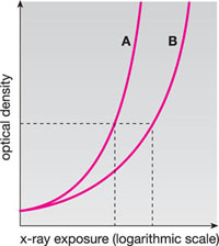
Fig 1-4 Characteristic curve for dental x-ray film(s). Optical density (vertical axis) indicates the “darkness” of the film. For the same density, film A requires less exposure than film B. Film A is, therefore, the faster film.
The size of the silver halide grains in the emulsion has a strong influence upon the ability of a radiograph to differentiate between structures that lie close together (resolution). Resolution is objectively measured by radiographing test/>
Stay updated, free dental videos. Join our Telegram channel
VIDEdental - Online dental courses


