Chapter 31 Root Form Surgery in the Edentulous Anterior and Posterior Mandible: Implant Insertion
The primary goal of root form surgery is to insert an endosteal implant into the available bone of an edentulous site in the proper location and angulation so that it may be used as a prosthetic abutment. An endosteal implant, made of biocompatible material, will predictably obtain rigid fixation when specific surgical principles are followed. The soft tissue should cover or approximate the implant for primary healing. The bone should receive as little trauma as possible. The smaller the devital zone, which forms around an implant subsequent to surgical trauma, the more likely rigid fixation will occur. The bone should initially be within 30 to 40 μm of the implant body,1 which should be rigidly fixated and not move during healing. Movement of 100 μm or more to the bone-implant interface has been shown to result in intervening fibrous tissue.2 The surgical site should remain free of infection, which may result in a bacterial smear layer on the implant body and impair the development of a close bone-implant contact during healing. The health, volume, and density of the recipient bone are critical to the preparation, fixation, and healing of an endosteal implant.
There are more than 100 types of root form implant designs readily available on the commercial market. A consistent philosophy is the desire for clinical rigid fixation corresponding microscopically to a direct bone-implant interface, without intervening fibrous tissue on a major portion of the implant body.3 The surgical procedures for endosteal root form placement are described in this book by region, bone volume, and bone density. This chapter addresses a generic surgical approach to the anterior and posterior mandible in adequate volume (Division A or B) and quality of bone (D2) for the placement of a screw-type root form implant.
SURGICAL APPROACH TO THE ANTERIOR MANDIBLE
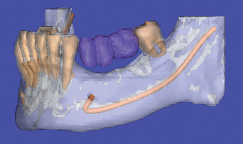
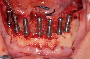
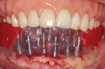
The most common location for root form implants in the completely edentulous mandible is between the mental foramina, in the region of the mandibular symphysis (Figure 31-1). The prosthesis type and amount of support for the patient force factors and bone density are first determined. If a fixed or RP-4 prosthesis is planned, most often five root form implants are usually indicated (see Chapter 14) in the A, B, C, D, and E positions (starting from the right of the patient to the left).4 Posterior implants may also be indicated, depending on the existing force factors and other parameters.
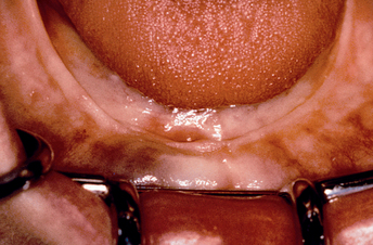
Figure 31-1 The most common position for root form implants in an edentulous mandible is between the mental foramina.
Panographic radiographs or computed tomography (CT) scan imaging is evaluated for potential pathology, bone volume, and anatomical landmarks such as mental foramina and crest of ridge. A lateral radiographic view may be taken with a transitional prosthesis in place, which permits the evaluation of bone volume in height, the angulation of the bone in the midline, and the crown/remaining bone height ratio. A surgical template is fabricated before surgery to indicate the incisal edge position of the final restoration and help determine proper implant location and angulation for the specific prosthesis (see Chapter 13). A standard surgical setup is prepared (see Figure 31-56).
Patient Preparation
The patient is prepared for surgery following the pharmacologic protocol typical for implant surgery (see Chapter 21). Because two carpules have a higher “hit” rate for block anesthesia, compared with one carpule, bilateral mandibular block anesthesia is administered with both lidocaine 2% 1:100,000 epinephrine and a long-acting anesthetic, such as bupivacaine (Marcaine) 0.5% with 1:200,000 epinephrine (Box 31-1). The use of a long-acting anesthetic is beneficial in three ways: (1) the added volume of anesthetic increases the success of the mandibular block; (2) a full arch mandibular implant insertion surgery may last 2 hours; therefore repeated injections at the end of the surgery are less indicated; and (3) in addition, long-acting anesthetics may reduce postoperative pain. In fact, it is advantageous to readminister the long-lasting block anesthetics at the conclusion of the surgery when its duration is longer than 1 hour.5
Akinosi Technique
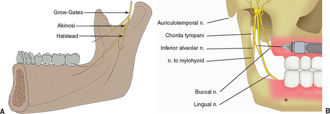
The Akinosi technique (closed mouth) for mandibular anesthesia is preferred in the completely edentulous patient, because the occlusal plane and opposing premolar position used as references for the traditional Halsted dental injections are unavailable or inaccurate (Figure 31-2).6 The Akinosi block procedure is administered with the mouth in an almost closed position or, because the patients often wear a denture, in an approximate occlusal vertical dimension. In addition, it is a benefit when the patient positions the jaw toward the side of the injection (i.e., slide the jaw to the right for a right mandibular block). A long, 27-gauge needle is used in the syringe. The needle is bent 30 degrees near the base, so the needle direction on a horizontal plane will be away from the midline. This is advantageous because the ramus flares lateral as it proceeds distal. The syringe and needle are placed parallel to the occlusal plane, at the height of the maxillary mucogingival junction. The needle penetrates approximately half its length (25 to 30 mm) before aspiration and injection of anesthetic. There is no bony landmark.
The Akinosi block is usually less painful for the patient, because the anesthetic fluid is injected into the top of the pterygoid triangular space, which has more room for the solution. In addition, the top of this triangular space has fewer muscle fibers in the pathway of the injection compared with the penetration site of the Halsted block and therefore is associated with less discomfort (Box 31-2).
Additional injections of anesthesia with the administration of local anesthetic (such as lidocaine 2% with epinephrine 1:100,000) by infiltration in the labial, lingual vestibules, and the inferior border of the anterior mandible are also required, because the inferior third of the mandible is innervated by cervical nerves (C2-C3). Typically, the injections are in the facial sites in front of the mental foramina and the midline, whereas the lingual injections are lingual to each canine region.
An extraoral and intraoral scrubbing and draping of the patient are then performed. The benefit of aseptic technique is well documented in general.7 However, a controversy exists regarding “sterile” versus clean surgical technique for endosteal implant placement.8,9 Both the clean and sterile techniques use instruments, implant components, and hand pieces that are sterile. An actual sterile environment cannot be achieved within the oral cavity10,11; therefore the term aseptic is often used.
A primary issue is the need to use sterilized gloves, gowns, patient drapes and covers for the light, hand piece cord, and evacuation tips. In addition, can the surgeon and assistant touch nonsterile items in the operating room? Scharf and Tarnow compared sterile versus clean conditions with 386 implants in 92 patients.12 Success rates were within 0.5% for the mandible and 1.6% for the maxilla. Kraut placed 2620 implants with a clean technique with a 1.26% surgical failure at implant uncovery and 0.5% early implant failure after function.9 Therefore these reports suggest the clean technique is adequate for implant surgery.
Brånemark Surgical Approach
The original Brånemark surgical approach was used in a hospital environment, with an aseptic protocol similar to orthopedic implants. There are several advantages to this approach. Normal skin flora, including Staphylococcus epidermidis and Staphylococcus aureus, are able to adhere to implanted biomaterials.13–15 A bacterial smear layer may develop, which will be difficult for the body to remove by phagocytosis or bone cell activity. Antimicrobial mouth rinses (e.g., chlorhexidine) significantly reduce bacterial count in the saliva for more than 4 hours.16 Chlorhexidine has been shown to reduce microbial complications when used perioperatively.17,18 Povidone-iodine alcohol solutions have antibacterial properties used in preoperative site disinfection.19 Although a sterile technique is not possible within the mouth, scrubbing around and within the mouth with these agents reduces the risk of a bacterial smear layer by inadvertent contamination by direct contact with the implant or indirectly via a glove or instrument.
The clinical decision for an aseptic versus clean environment rests with the individual clinician, because documentation exists for either approach. However, it is prudent to reduce the risk of infection preoperatively and postoperatively. Although rare, infection may occur as a postoperative complication. Intraoral surgery is assimilated to a class II or clean contaminated surgery. Incidence of infection for class II surgery is 10% to 15%, but can be reduced to about 1% if appropriate technique and prophylactic antibiotics are prescribed.20 The risk of infection with endosteal implants when preoperative and postoperative antibiotics are used appears to be even less.9,21,22
What Is Clean?
More invasive procedures such as sinus bone grafts exhibit a range of postoperative infection from 3% to 20%.23,24 Based on this, the author suggests that an aseptic surgical procedure be used for most sinus surgeries. For full-arch implants or bone grafts, larger regions of tissue are exposed with increased risks to patients if infection occurs, so aseptic technique should be considered. In many dental offices the staff needs constant retraining for procedures that are not often performed. The routine aseptic surgical approach ensures the quality and consistency of the asepsis when it is most indicated.
Intraoral and extraoral scrubbing with iodine, povidone-iodine (Betadine), or 0.12% chlorhexidine gluconate may be performed by a scrubbed assistant. A surgical scrub and gowning is performed by the doctor during the patient preparation. On return to the operating room, the patient’s final drapes are positioned. The surgical gloves are rinsed and wiped with sterile saline to remove any powder or contaminant that may be inadvertently transmitted on the implant surface during the subsequent surgery. Infiltration with 2% lidocaine with 1:100,000 epinephrine into the labial and lingual mucoperiosteum evaluates the depth of anesthesia and provides some initial hemostasis. In addition, when the local anesthetic is placed under the periosteum along the crest of the ridge, a hydroelevation of the soft tissue may help initial reflection of the soft tissue.
Incision
After anesthesia is achieved, the soft tissues and ridge height are evaluated. The lingual aspect of the mandible is palpated for undercuts and compared with the radiographic diagnostic images. Identification of the approximate position of the mental foramen facilitates the incision line design in moderately to severely atrophied mandibles and allows a more rapid reflection in regions around this landmark. The mandibular foramen region may be located by several methods. Palpation for the depressed foramen has been advocated, but is the most variable.7 The overlying tissues usually prevent adequate feeling to identify the foramen with certainty.
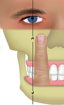
Before the patient is surgically draped for the procedure, an imaginary line may be drawn between the pupils of the eyes. A perpendicular line may then be drawn through each pupil (Figure 31-3). This vertical line passes through the infraorbital foramen and mental foramen. A surgical pen is used to mark the gingival tissue over the mental foramen region. If the patient is draped and the eyes cannot be used as a landmark, the foramen region corresponds to a vertical line drawn one fingerwidth distal to the ala of the nose and slightly distal to the corner of the mouth.
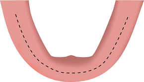
Because suture line opening is the most common immediate postoperative complication, the surgical incision is designed to minimize this problem. If the crest of the ridge is above the floor of the mouth and there is greater than 3 mm of attached, keratinized gingiva on the crest of the ridge, a full-thickness incision is made, bisecting the attached tissue and scoring the bone on the crest of the ridge from the first molar region on one side to the anterior region and to the contralateral first molar region (Figure 31-4). If less than 3 mm of attached gingiva exists on the ridge, the full-thickness incision is placed so that at least 1.5 mm of the attached tissue is to the facial aspect of the incision line. This zone of attached tissue on the facial flap provides greater resistance for the sutures against tension of the mentalis muscle in the anterior region and buccinator muscle in the molar-premolar regions, which often cause the incision line opening. In addition, the blood vessels from the lingual artery may not cross over the crest of the ridge, but instead stop within the attached tissue.25 As a result, an incision made facial to the attached tissue may cause partial ischemia to some of the crestal tissue. In addition, the incision in unkeratinized facial tissue also severs larger blood vessels, which increases bleeding and decreases vision during surgery. The incision should be done in one pass through the mucosa and periosteum and precisely score the periosteum. Additional scoring of the crestal bone after the initial incision design is usually beneficial. Areas of soft tissue invagination in prior extraction sockets are excised so as to create a clean margin for the flap, devoid of epithelium.
SOFT TISSUE REFLECTION–LANDMARK IDENTIFICATION
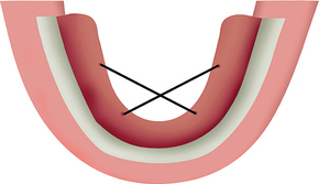
A periosteal elevator (e.g., Molt 2-4, Molt A-1, Molt 7 or 9) is used to reflect a full-thickness flap. The mucoperiosteal flap is first reflected on the lingual aspect, which is typically less tenaciously attached to the underlying bone. The lingual reflection begins in the regions of the canine and proceeds to the molar region on the same side. The contralateral canine to molar region is then reflected. This phase of the procedure most often is performed within a few seconds. The lingual flap between the canines is then reflected. This region is more difficult to reflect, because some of the tissues are embedded into the residual alveolar crest. Retraction (tie-back) sutures with 2-0 silk are then used to keep the lingual flap out of the surgical site. The right lingual canine region is tied to the left molar area, and vice versa. The sutures engage at least 5 mm of tissue, with care taken to avoid the submandibular duct. The lingual flap retraction improves visibility, negates repeated surgical assistant retraction efforts during the procedure, and reduces trauma to the thin lingual periosteal tissues (Figure 31-5).
After a full-thickness periosteal flap is reflected, the periosteum must regenerate from the unreflected portion before this structure can participate in crestal bone healing.26 Although adequate reflection to identify all bony landmarks is necessary, overzealous reflection increases soft tissue trauma and may delay bone callus formation around the implant, which may contribute to crestal bone healing.
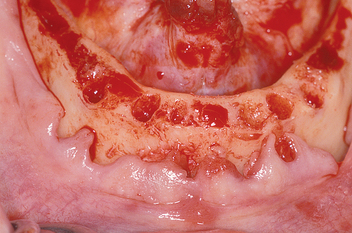
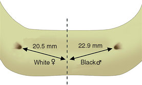
The facial flap is then reflected. The exact location of the mental foramina and associated nerves, arteries, and veins are identified (Figure 31-6). These are essential surgical landmarks. An anthropometric analysis of the position of the mental foramina was performed by Cutright et al.27 The average distance from the midline was 2.2 cm, which means the usual distance between the foramina is 44 mm. Because at least 7 mm of mesiodistal bone are usually required for each 4-mm-diameter implant, the average anterior mandible has room for six implants. However, the mental foramina position is variable, depending on race, sex, and skull size. The average interforamen distance for black males was 45.8 mm; white males, 45 mm; black females, 43.8 mm; and white females, 41 mm. Therefore white females often do not have room for six implants between the foramina (Figure 31-7).
When the mental foramen position is related to a tooth position, it may reside as far anterior as the canine to first premolar position, or as far distal as the second premolar to first molar root position.28–31 The farther distal the foramen (and neurovascular canal), the farther distal the most distal implant (A and E sites) and the better the biomechanics for the prosthesis. When the foramen resides in its most distal position, six implants may be positioned between the foramina. When the foramen resides in its most anterior position, only four implants may be inserted to leave 3 mm of space between each implant. The most common mental foramina sites are between the first and second premolar roots, but they may be present below either the first or second premolar root. Under this condition, five implants may be positioned between the foramina.
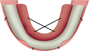
Because the primary incision was extended to the first molar region, the approach to the foramina can proceed from both anterior and posterior, which facilitates their identification. After the periosteum is reflected off the residual crest, a moist surgical sponge can be used to wipe the periosteum off the dense labial cortical plate around each foramen. This permits rapid and safe exposure of the nerve complex without trauma from instruments. Soft tissue reflection is limited in the mandibular symphysis region to avoid ptosis of the chin, which may occur after overzealous reflection of the mentalis muscles’ lower attachments in moderately to severely atrophied mandibles. Tie-back sutures may be positioned to retract the facial flap during surgery. Most often these are placed in front of the mental foramen (Figure 31-8). All fibrous tissue is removed from the crest of the edentulous ridge. A bone rongeur, followed by a moist surgical sponge rubbed across the crestal surface, eliminates most fibrous adhesions.
If the mandibular canal approaches the foramen at the same height, the nerve always enters the distal portion of the foramen. When this is clearly identified on the panoramic radiograph, the foramen is used as the distal landmark. The panoramic radiographs or CT images are observed to visualize a possible anterior loop of the mandibular neurovascular canal. A mandibular loop occurs when the mandibular neurovascular canal approaches the foramen from below, proceeds anterior to the foramen about 1 to 3 mm, and curves upward and distal to enter the medial aspect of the mental foramen (Figure 31-9). This has been observed almost 12% of the time for a distance of 1 to 3 mm on panoramic radiographs.32 On the other hand, Rosenquist dissected 58 inferior alveolar neurovascular bundles and identified a 1-mm anterior loop in 43 cases.33 A study on dry skulls noted anterior loops of 2 mm or more on 92% to 96% of the specimens.34 Surgical dissection provided by Solar et al.35 showed an anterior loop in 60% of mandibles ranging from 0.5 to 5 mm. Neiva et al. identified loops in 88% of cases with a range of 1 to 11 mm.36 Dissection studies with comparison to radiographs were performed by Bavitz et al.,37 who reported 54% of loops in periapical radiographs, but only 11% where verified by dissection. Other studies concurred with the conclusion that a high percentage of false-positive or false-negative findings may occur.38,39 For such a topography, the most distal anterior implants are placed 2 mm anterior to the anterior loop, which becomes the landmark rather than the mental foramen itself (Figure 31-10).
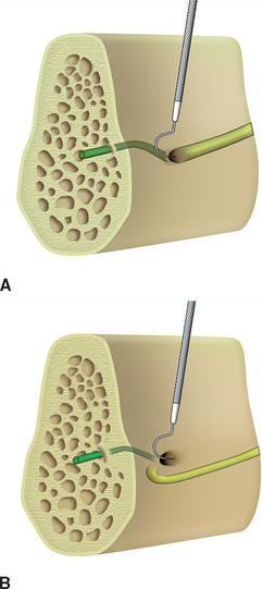
On occasion, the nerve complex around the foramen is not clearly identified on traditional films. An anterior loop may or may not be present. A CT scan of the region may provide the information needed. Another option is to determine whether there is an anterior loop during surgery. A curved Naber’s 2N probe may be gently inserted inside and along the bone on the distal half of the foramen to determine whether the nerve proceeds from the posterior region directly into the foramen. If no nerve entry is felt along the distal half of the foramen, the nerve must loop anteriorly and enter from the anterior aspect (Figure 31-11). Probing the anterior half of the foramen is not diagnostic, because the mental nerve complex continues anteriorly from the foramen to innervate anterior teeth and bone, regardless of whether there is an anterior loop. Therefore there is always a canal entering the anterior portion of the foramen.
The prosthesis must replace the vertical bone height removed during the osteoplasty. If a fixed prosthesis is the final prosthesis, care is taken to carefully evaluate the amount of bone reduced. Whenever an osteoplasty is performed, the bone is harvested and stored in sterile saline in case an autogenous graft is required during a later step of the surgical procedure.
Implant Site Preparation
Rotary instruments are used to prepare the implant site. Regardless of implant design or manufacturer, several surgical concepts are crucial for initial rigid fixation. A primary criterion is to limit thermal or mechanical trauma to the surrounding hard tissues (Box 31-3).40–55 Bone is very susceptible to heat.40 Heat is generated by the drill during the implant osteotomy. A major method to reduce the bone temperature during drilling is the use of cooled irrigation.41,42 A secondary method to reduce heat and thermal trauma is related to the amount of bone removed with each drill.41,45 Therefore sequencing drill diameters should prepare the final osteotomy site. The drill speed and time during which the bone is prepared is one of the major factors related to bone trauma.48,49 Additional factors such as internal versus externally cooled drills are less important.48,55 A detailed discussion of these factors is presented in the bone density–a surgical approach (see Chapter 29).
Implant Site Location
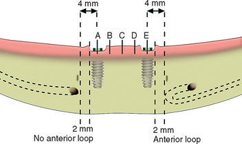
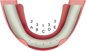
After the midline implant site (C) is determined, the boundary score lines on the crest of the ridge that correspond to the anterior limit of the mandibular canal are identified. A pilot hole is made with a No. 6 round bur or pilot drill placed 4 mm medial to each distal score line (if the implants are 4 mm in diameter) to determine the center of the most distal A and E implants. This provides 2 mm of surgical error away from the boundary that identifies the mandibular nerve during bone preparation and implant placement. The distance between the midline pilot hole and distal pilot holes are then equally divided for the B and D implants. They also can be mapped with a measuring tool. The distance between each implant center site should be at least 7 mm, or 3 mm between the 4-mm-diameter implant bodies. Larger-diameter implants require more than 7 mm between each center pilot hole (i.e., 8 mm for 5-mm-diameter implants) (Figure 31-12).
The initial pilot drill is used at a depth of 5 mm and evaluates the density and thickness of cortical bone on the crest of the ridge, if any remains after the osteoplasty. It can also be used for initial bone preparation in the narrow ridge. This end-cutting bur can prevent lateral perforations because it will roll away under light pressure from the harder inner cortical plate and stay within the softer trabecular bone. A No. 6 bur or a Lindemann drill may also stretch a hole in any direction to improve its final position. For example, if the initial bur hole is too lingual, the #6 or Lindemann bur can be used in the initial site to create an oblong hole more facial. As long as the initial hole is less than 2 mm from the ideal site, the final osteotomy and implant will completely obtund the initial erroneous pilot hole. In this way, the ideal location is finalized before the initial osteotomy is begun.
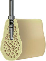
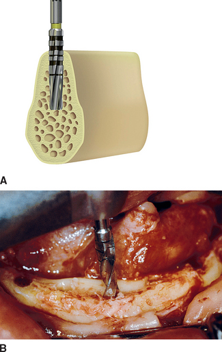
The center implant site (C) is prepared first with the 2.0-mm-diameter pilot drill for the initial depth of bone preparation of 9 mm (Figure 31-13). This position should be perpendicular to the occlusal plane. If one marginal crest of bone is higher than the other (usually the lingual), the osteotomy depth is measured from the most inferior edge such that the implant body is positioned slightly below the lingual crest of the ridge.
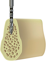
Figure 31-13 A 2-mm-diameter pilot drill is used to prepare the center implant site for 9 mm, perpendicular to the occlusal plane.
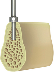
A direction indicator (parallel pin) is placed into the center implant site (Figure 31-14). Angulation is checked in a labiolingual and mesiodistal direction with the surgical template, which may be facilitated with guidance from an assistant (preferably standing over the midline at the foot of the chair) (Figure 31-15). The osteotomy is often not prepared while the template is in place. The implant site must have adequate bone on the labial and lingual aspects. This requires direct vision and careful observation of both cortical plates while preparing the bone. A pumping motion is used to prepare the site to the radiographically determined depth; however, this dimension is reevaluated and may be changed at this time. The bone density is noted during the initial osteotomy preparation. The procedures described in this chapter are for D2 bone density.
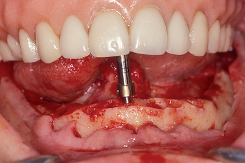
After the initial sites are prepared with the pilot drill, small-diameter (2 mm) direction indicators are used in the initial implant preparations to evaluate the need for any minor adjustments (Figure 31-16). The surgical template is inserted to evaluate implant angulation and position (Figure 31-17). If the angulation is incorrect by less than 20 degrees, it can usually be corrected with the next drill in the sequence provided by the manufacturer. If the angulation is to be modified by more than 20 degrees, a side-cutting drill (e.g., Lindemann) rather than end cutting is most efficient. These side-cutting drills also can stretch the initial osteotomy laterally to improve the implant position. If the angulation is beyond 30 degrees to an axis perpendicular to the occlusal plane, or if the osteotomy is too lingual or facial in relation to the incisal edge, correction of the initial osteotomy should precede any further bone preparation. The oblong osteotomy prepared to correct the problem of poor position or angulation is obliterated and made round again with successive drills of incremental diameter.
After the direction indicator confirms proper implant position, the osteotomy is made to the full depth of the planed implant size (Figure 31-18). It is usually better to drill 1 mm deeper than needed (i.e., 13 mm for a 12-mm implant) when the opposing landmark permits. If the opposing landmark is perforated before obtaining the desired length of the osteotomy, the osteotomy length before perforation is noted, and a shorter-length implant is selected. Ideally, the implant should not perforate the mandible to avoid irritation of the soft tissue, especially for a sharper apex implant design, where even slight perforation may irritate the tissues. If the implant has an open basket design, a perforation may trigger fibrous tissue ingrowth within the basket, rather than bone.
The anterior mandible may present a significant undercut on the lingual aspect between the foramina. Life-threatening hemorrhage has been reported when a drill perforates the lingual plate of the sublingual region of the mandible and injures a sublingual or submental artery, especially in the canine region.56–59 If perforation of the lingual cortical plate is associated with arterial bleeding, it is critical to identify its origin (Table 31-1). Bleeding in the floor of the anterior region of the mouth can originate from the lingual artery, facial artery, or one of its branches. The submental artery originates from the facial artery, runs along the inferior border of the mandible, and meets at the midline. Pressure over the genial angle notch (just anterior to the masseter muscle) stops this type of bleeding. If the injured artery stems from the lingual artery, the bleeding will be reduced when the tongue is pulled out, thus placing pressure against the lingual artery where it crosses over the hyoid bone. Elevating the head is also of benefit. After the bleeding is reduced, it may be stopped by collagen sponges or hemostasis after clot formation, or rarely by surgical ties or electrocautery (see Complications).
Table 31-1 Treatment of Hemorrhage at Implant Osteotomy Site
| BLEEDING SITE DURING IMPLANT OSTEOTOMY | ARTERIES | TREATMENT |
|---|---|---|
| Posterior mandible | Mylohyoid | Finger pressure at the site |
| Middle lingual of mandible | Submental | Surgical ligation of facial and lingual arteries |
| Anterior lingual of mandible | Terminal branch of sublingual or submental | Compression, vasoconstriction, cautery, or ligation |
| Invading the mandibular canal | Inferior alveolar artery | Bone graft |
A critical step in obtaining rigid osseous fixation after initial implant placement is to maintain a rigid bone-implant interface without micromovement between the time of original placement and the second stage of surgery. The implant does not have to be submerged below the bone to achieve this result. The implant does not even need to be below the soft tissue to obtain this type of interface.60,61 However, the clinician should recognize situations such that the higher the implant is placed above the bone, the greater the risk factors for trauma that may result in movement at the interface during initial healing. As a result, when an overlying soft tissue–borne prosthesis is worn, it may be advantageous to countersink the implant below the bone. On the other hand, when a prosthesis abutment is added to the implant crest module below the bone, approximately 0.5 mm of soft tissue forms below the abutment-to-implant connection.62 Therefore, if the crest module of the implant was below the crestal bone at the time of surgical placement, crestal bone loss will occur when the abutment is added.
Drills of intermediate diameter are used next for the implant bone preparation. Gradual increases in drill diameter reduce the amount of pressure and heat transmitted to the bone, especially in presence of dense and thick cortical bone. Lavelle has shown the heat generated from a drill can be transmitted more than 3 mm away from the osteotomy site and reach temperatures higher than 50°C under copious irrigation.50 The 2.0-mm initial drill is followed by a 2.5 mm drill, and then a 3.0- or 3.4-mm drill (Figure 31-19). Some manufacturers do not use an intermediate drill; however, a decrease in the heat and trauma generated is found with the intermediate drill.53 The softer the bone, the fewer the number of intermediate drills needed. Direction indicators are placed in bone sites medial or lateral to implant sites being prepared. Minor corrections in angulation should be accomplished during these intermediate drilling steps.
The final drill diameter is used to prepare the implant receptor site under copious irrigation (Figure 31-20). This step is the most critical for initial implant insertion and healing. The bone surrounding this drill will be in direct contact with the implant. When the final drill preparation is not precise, the implant-bone region may be incongruent and gaps may decrease initial stability, which may lead to early failure. A lesser initial contact with the host bone also decreases the percentage of new bone-implant contact formation.54 Therefore a constant pressure and direction is used with the final drill to ensure a precise, round osteotomy is prepared along with direction indicators in adjacent sites to maintain the proper angulation. A summary of potential problems during implant osteotomy preparation and suggested solutions is presented in Table 31-2.
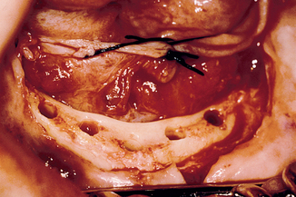
Table 31-2 Possible Problems Encountered during Root Form Surgery and Suggested Solutions
| PROBLEMS | SOLUTIONS |
|---|---|
| Improper pilot hole/location | Create a new pilot hole with round bur No. 6 or stretch the existing hole with a No. 6 drill or a side-cutting drill (e.g., Lindemann). |
| Improper drilling angulation | Start a new direction with the pilot drill and 1.5-mm drill and continue with remaining procedures. Use a side-cutting drill to redirect the osteotomy. Use the assistant/doctor force direction indicators or template to regularly check direction during the osteotomy preparation. |
| Elliptical/eccentric preparation | Continue the surgical procedures and try to use the planned implant. If the implant is loose on seating, use a wider-diameter implant if possible. If not, pack the osteotomy with autogenous graft, compress it, and place implant again. If the angle with the adjacent implant is greater than 30 degrees, remove the implant and allow the surgical site to heal for approximately 6 months. Place the implant at a later date. |
| D1 bone density | Prepare osteotomy with a constant pumping motion to avoid overheating and use higher torque and speed. Use new drills and profuse irrigation with incremental drill sequence. Use bone tap with hand ratchet. |
| D3-D4 bone | Push the drill as it rotates at decreased speed. Do not bone tap. Insert implant with hand piece. |
| Perforated buccal or lingual bone plates | Stop drilling as soon as less than 1.0 mm of bone is lateral to the drill. Use an osteotome with a tapered end to expand the osteotomy, rather than removing the bone with a drill. |
| Threads exposed at crest of ridge | If implant threads are exposed coronally, graft autogenous bone harvested intraorally with rongeurs or a trephine bur over the region. |
Stay updated, free dental videos. Join our Telegram channel
VIDEdental - Online dental courses


