Full rehabilitation of the maxilla and mandible
If the patient is not yet totally convinced of the advantage of implant treatment, and the main priority is for him or her to have the positive experience of a speedy and reliable outcome, then it is better to start with the mandible.
3D diagnosis
The diagnosis and planning for the two jaws separately have already been discussed in the relevant chapters. Where an overall concept is involved, the planning for both jaws should also be coordinated logistically and with regard to timing. An advantage in this type of planning is that a single cone beam computed tomography (CBCT) scan is usually sufficient to plan treatment in both jaws.
3D planning for implant placement in the maxilla and a Sliwowski Overdenture System (SOS) in the mandible
An edentulous woman wanted a fixed restoration in both jaws. A CBCT scan was taken. Both jaws, especially the mandible, still appear well-preserved. The maxilla seems to be of sufficient height, but the anterior segment appears very narrow (Fig 7-1a). A total of eight implants were planned in the maxilla; only narrow platform (NP) implants were an option in the anterior maxilla (Fig 7-1b). In the posterior maxilla, the residual ridge was wide enough, but its quality was insufficient for the insertion of regular platform (RP) implants (Fig 7-1c). Bone density around the planned implant in position 16 was approximately 0 Hounsfield units (which corresponds to the density of water). In region 26, the bone was softer still, its density being even less than 0 (Fig 7-1d). In the anterior maxilla, the residual ridge was harder and its density around implant 23 was much more favorable. However, it was so narrow that augmentation was required (Fig 7-1e).
Planning in the maxilla was followed by implant placement planning for the mandible using the same CBCT scan images. In the mandible, the initial plan was to insert five implants in the interforaminal region to support a fixed cantilever bridge (Fig 7-1f). However, once the planning was complete, it emerged that the patient could not afford the full treatment at that time. Following a detailed consultation with her, it was decided that implant placement in the maxilla would be performed first. The mandible was to be treated in the next stage, but the financial investment associated with it needed to be considerably reduced. As part of the overall plan, the intention was to start with the more affordable Sliwowski Overdenture System (SOS) treatment in the mandible. A new CBCT scan with a template with integrated markers and a housing replica for the planning software coDiagnostiX (Dental Wings) was performed to plan implant placement in the mandible (Fig 7-1g). Two parallel implants at a distance of exactly 18 mm, positioned at the center of the interforaminal region, were planned. This scan provided the opportunity to evaluate implant placement in the maxilla, which had taken place in the interim. As planned, the apex of implant 16 was anchored in the cortical septum between the maxillary sinus and the nasal cavity (see Figs 7-1c and 7-1h).
For the treatment course, see page 520.
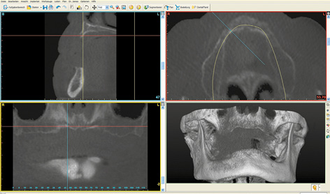
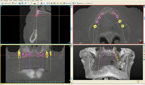
Fig 7-1b Eight implants have been planned in the maxilla.
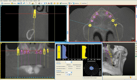
Fig 7-1c Poor bone quality around implant 16.
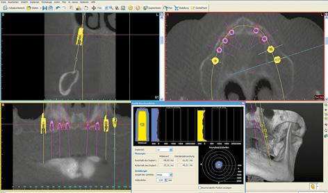
Fig 7-1d Even softer bone around implant 26.
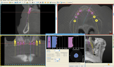
Fig 7-1e Narrower but harder residual ridge in region 23.
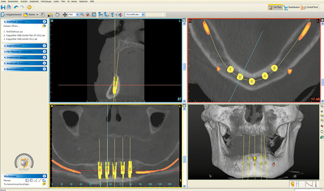
Fig 7-1f Five interforaminal implants have been planned for a fixed cantilever bridge.
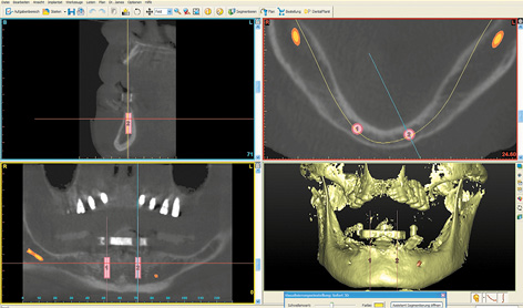
Fig 7-1g Change in plan for the Sliwowski Overdenture System (SOS) treatment.
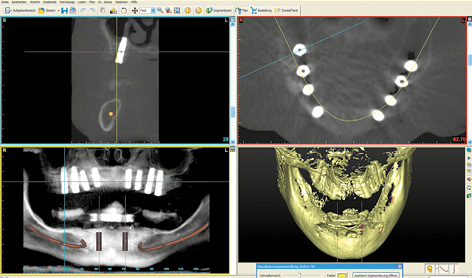
Fig 7-1h Checking implant placement in the maxilla. Bicortical anchoring of implant 16.
3D planning for sinus elevation in the maxilla and implant placement in the mandible
This male patient wanted a fixed restoration in both jaws. There were still a few teeth left in both jaws; these were being used to anchor the overdentures. His existing prostheses were to remain in use until the definitive superstructures were incorporated onto the implants.
In the maxilla, the maxillary sinuses on both sides were so pronounced that sinus elevations would also need to be performed before implant placement (Fig 7-2a). Both maxillary sinuses contained a few septa, which could complicate dissection of the maxillary sinus mucosa. Since the operation was to be performed under general anesthesia, implant placement in the mandible was scheduled to take place along with the sinus elevation (Fig 7-2b). The plan was to place a total of eight implants for a fixed restoration in the mandible. Four long implants were to be inserted in the interforaminal segment, plus two per side in the posterior region (Fig 7-2c). The implants in the mandible were aligned to the dentition of the maxilla (Fig 7-2d). Clear visualization of the alveolar nerves facilitated implant planning in the posterior regions (Fig 7-2e). In the cross sections, the implants were planned to ensure that the distance between implant and nerve was not less than the 2-mm limit (Fig 7-2f). If the residual ridge was wide enough, the plan was to insert implants with a diameter of 4 mm (shown in yellow here). In the anterior segment, the residual ridge was much narrower, so that long implants, but with a reduced diameter of 3.5 mm (shown in green) were been planned here (Fig 7-2g).
For the treatment course, see page 539–543.
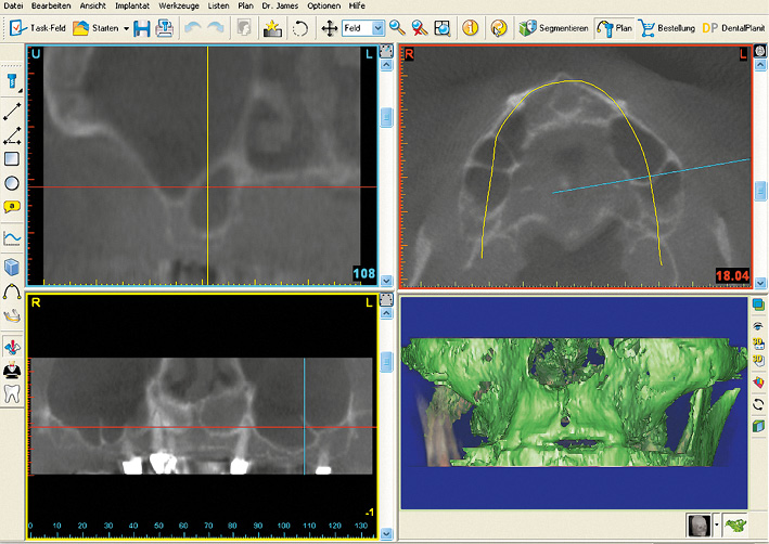
Fig 7-2a Very pronounced maxillary sinuses with several septa.
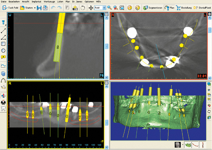
Fig 7-2b SimPlant implant planning for the mandible.
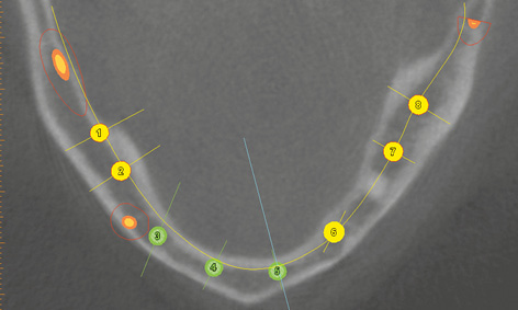
Fig 7-2c Uniform distribution of the implants in the mandible.
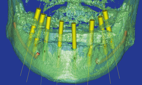
Fig 7-2d The implant axes have been aligned to the dentition in the maxilla.
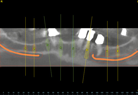
Fig 7-2e The alveolar nerves in the mandible have been marked in red.
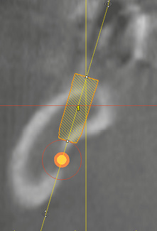
Fig 7-2f The minimum distance between implant and nerve is 2 mm.
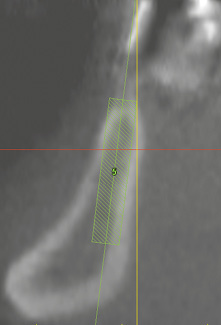
Fig 7-2g High, but narrow residual ridge with corresponding implant.
Bar structures with locking attachments in both maxilla and mandible
This treatment course follows on from the 3D diagnosis on page 516.
Baseline situation
A 60-year-old, edentulous woman, who is a heavy smoker, wanted a fixed restoration in both jaws. The placement of implants in both jaws was planned in accordance with her wishes using SimPlant (Dentsply) (see 3D diagnosis, page 516). However, the patient’s financial means were limited at that time, so her wishes could not be realized in full. As a compromise, we agreed to provide her with a fixed restoration of the maxilla straightaway, while performing the SOS treatment in the mandible as an interim solution. The patient had the option to have additional implants placed in the mandible at a later date, and to have the restoration fabricated using the SOS method reworked into a fixed implant bridge.
Diagnostic tools
- Clinical examination
- Panoramic radiograph
- CBCT and planning with the SimPlant program
- Repeat CBCT: the patient with mandibular template and the template alone
- SimPlant planning and SOS SurgiGuide (Dentsply) drill guide for the mandible
Treatment plan
1.Implant placement in the maxilla
2.Implant placement and direct prosthetic loading in the mandible
3.Exposure and definitive prosthetic loading in the maxilla
Implant placement in the maxilla
The patient’s maxilla appeared to be very well preserved, both in the CBCT scan images (see 3D diagnosis, on page 516; Fig 7-1a, page 517) and on clinical inspection (Fig 7-3a). Implant placement took place under general anesthesia. As planned, the Replace Select NP implants (Nobel Biocare) were inserted into the positions of the canines and first premolars (Fig 7-3b). Implants 18 mm long and 4.3 mm in diameter were placed in the posterior region. As already expected at the planning stage, the bone was very soft, so that there would be virtually no primary stability for implant 26 following drilling with the 3-mm twist drill. The machine was stopped at 5 N/cm, as it would otherwise have driven the implant in further. Because of the very soft bone and the consequently doubtful prognosis, especially for implant 26, the patient was requested to stop smoking and the healing period was extended to 10 months. The residual ridge was then augmented with the harvested bone chips. The postoperative panoramic radiograph shows the implants, distributed according to the plan (Fig 7-3c).
Implant placement and SOS restoration in the mandible
Implant placement and direct prosthetic loading in the mandible with the SOS method was planned 2 months after implant placement in the maxilla (see Fig 7-1g, page 517). The mandible was both radiologically and clinically very well suited for this treatment (Fig 7-3d). Using the prepared drill guide and special instruments, two implant beds were prepared for the SOS implants (Fig 7-3e). The exact procedure is described in Chapter 3, “The Edentulous Mandible” (see page 119). The next day, the reworked prosthesis was incorporated on the prefabricated bar in the mandible (Fig 7-3f).
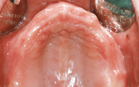
Fig 7-3a Edentulous maxilla before treatment.
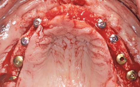
Fig 7-3b The eight inserted implants before augmentation.
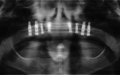
Fig 7-3c Postoperative panoramic radiograph.
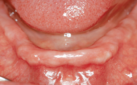
Fig 7-3d Edentulous mandible.
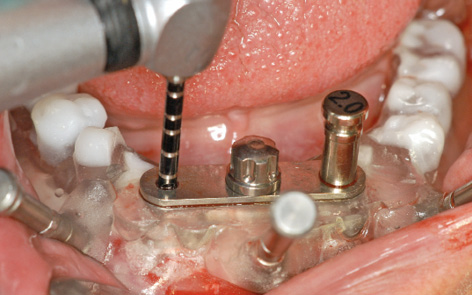
Fig 7-3e SOS treatment.
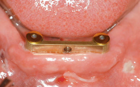
Fig 7-3f Prefabricated SOS bar 1 day after surgery.
Exposure and prosthetic loading in the maxilla
Eight months later, the implants in the maxilla, already partly visible through the mucosa, were ready for exposure (Fig 7-3g). The patient had followed our advice and had not smoked any cigarettes throughout her treatment period and had managed to quit smoking completely. Corrective measures for the mucosa and the procedure to widen the zone of attached gingiva around the healing abutments were performed at the time of implant exposure (Fig 7-3h). Three weeks later, the gingival situation had stabilized, allowing an impression to be taken (Fig 7-3i). A panoramic radiograph was taken after the impression copings were fitted (Fig 7-3j). This also provided the opportunity for a radiologic check of the implants in the mandible. A custom-made bar on eight implants was fabricated in the laboratory using the computer-assisted design/manufacturing (CAD/CAM) technique and screwed onto the implants (Fig 7-3k). The prosthesis made to fit this was based on an electroplated gold framework and included two MK1 attachments, providing considerably greater stability than the central attachment in the mandible (Fig 7-3l). To remove the prostheses, both attachments would need to be pushed toward the palate for the maxillary denture, and just one lingual for the mandibular one; the prostheses were now unlocked (Fig 7-3m).
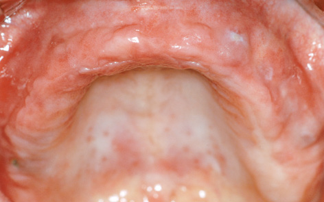
Fig 7-3g Implants showing through the mucosa.
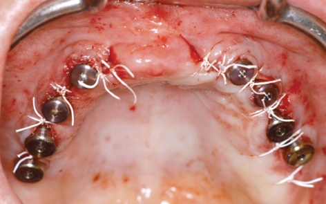
Fig 7-3h Exposing the implants.
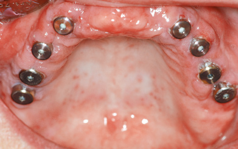
Fig 7-3i Situation prior to impression taking.
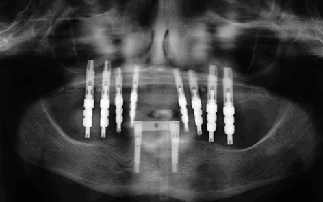
Fig 7-3j Panoramic radiograph to check the positions of the impression copings.
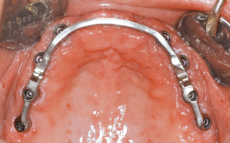
Fig 7-3k Connector bar fitted to the maxilla.
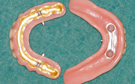
Fig 7-3l Maxillary prosthesis with two locking attachments and mandibular prosthesis with one attachment.
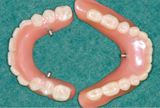
Fig 7-3m Occlusal view of both prostheses.
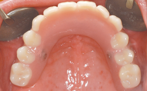
Fig 7-3n Maxillary prosthesis locked into place.
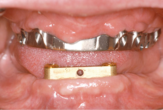
Fig 7-3o SOS bar after 1 year of functional use.
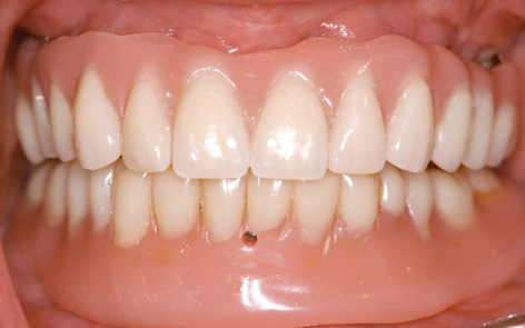
Fig 7-3p Anterior view of both prostheses.
Once the prostheses were inserted, the attachments were locked, after which they were virtually undetectable with the tongue (Fig 7-3n). Of course, the prosthesis was designed to be palateless. The patient was very satisfied with her treatment and radiantly happy about her securely fitting fixed dentures. One year after treatment completion, the gingival situation in both jaws showed nothing of note (Fig 7-3o). Potential further treatment in the mandible was discussed. The patient’s financial situation had improved significantly, but she was so happy with the restoration in her mandible that she wanted no change and described the SOS method as an ideal restoration (Fig 7-3p).
Treatment course
- Implant placement in the maxilla (2011)
- 2 months to the SOS treatment in the mandible
- 8 months to exposure in the maxilla
- 2 months to prosthetic loading
Treatment
|
Surgery: |
Dominika Sliwowska, DDS Dr Christoph T. Sliwowski |
|
Prosthetics: |
Dominika Sliwowska, DDS |
|
Dental technology: |
Dental Technician Ludger Jansen, DentaLab |
Typical treatment course
Sinus elevation and subsequent implant placement, reconstruction of the gingival zone
Baseline situation
A 62-year-old man’s dentition required urgent attention (Fig 7-4a). He wanted a fixed restoration in the maxilla and mandible, if possible one that he could wear throughout his treatment period. In view of the patient’s denture phobia, three anterior teeth were left in each jaw to allow him to be fitted with a fixed provisional restoration during the healing period (Fig 7-4b). Long-term, metal-reinforced provisional restorations were fitted on these teeth (Fig 7-4c). The maxilla required bilateral sinus elevation to be performed first. The shadows in both maxillary sinuses, particularly the right, presented additional problems. In the mandible, a post-extraction healing time of 2 months was to be followed directly by SimPlant planning and preparation of implant placement (Fig 7-4d).
Diagnostic tools
- Clinical examination
- Panoramic radiograph
- CBCT
- SimPlant planning
- Dental cast analysis
Treatment plan
1.Dental treatment including extractions
2.Bilateral sinus lift and implant placement in the mandible
3.Implant placement in the maxilla
4.Exposure and definitive prosthetic loading
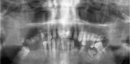
Fig 7-4a Panoramic radiograph before dental treatment.
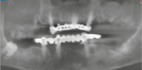
Fig 7-4b Panoramic radiograph with the long-term provisional restorations.
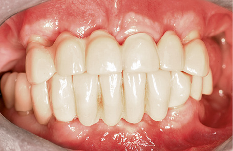
Fig 7-4c Fixed provisionals, each supported on three teeth in the maxilla and mandible.
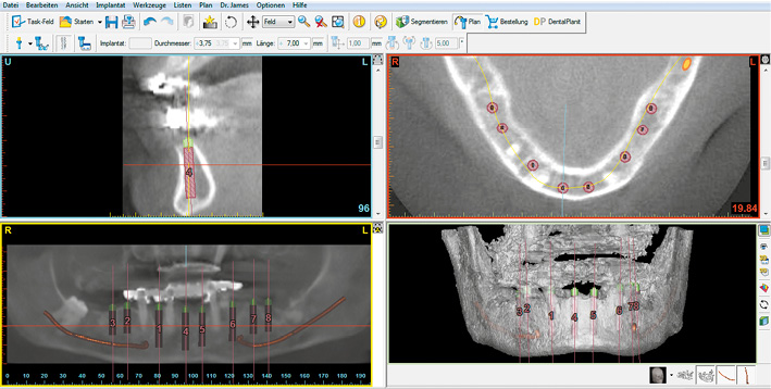
Fig 7-4d SimPlant planning for the mandible.
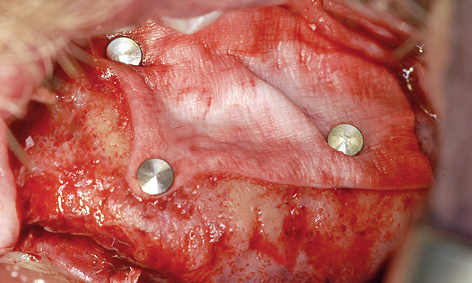
Fig 7-4e Sinus elevation.
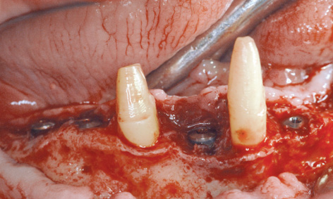
Fig 7-4f Implant placement in the right mandible.
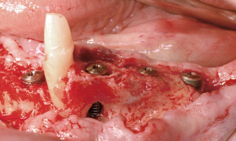
Fig 7-4g Implant placement on the left side of the mandible.
Bilateral sinus lift and implant placement in the mandible
Working under general anesthesia, the sinus floor augmentation was performed on each side of the maxilla, as planned (Fig 7-4e). Directly afterwards, implants 42, 44, 46 and 47 were inserted into the right side of the mandible (Fig 7-4f). The bone defects (especially around implant 44) were augmented with the harvested bone chips and a Bio-Gide (Geistlich) membrane. Only the canine remained in the left side of the mandible, so that one implant was placed in the anterior mandible and three in the posterior mandible (Fig 7-4g). In addition to the marginal defect, which remained after the extraction, implant 34 also showed an apical fenestration (Fig 7-4g). Augmentation was performed around all the implants.
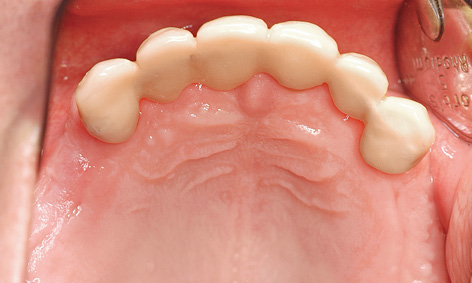
Fig 7-4h The maxilla before implant placement.
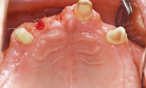
Fig 7-4i Visible residual ridge defects following removal of the fixed provisional bridge.
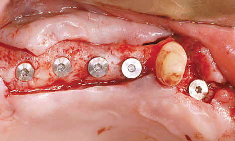
Fig 7-4j Implant placement on the right side.
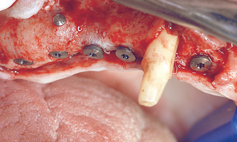
Fig 7-4k Implant positioning has been used to compensate for differences in residual ridge height.
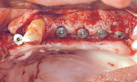
Fig 7-4l Implant placement on the left side.
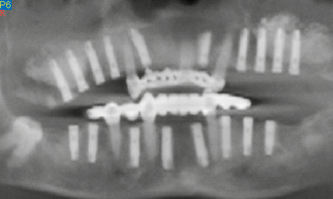
Fig 7-4m Panoramic radiograph after the implantation.
Implant placement in the maxilla
Eight months after the sinus elevation, the maxilla was ready for implant placement (Fig 7-4h). Pronounced bone defects were apparent as a result of the prior dental treatment and extractions, especially in the anterior segment (regions 12, 11 and 22; Fig 7-4i). On the right side, the implants were distributed so that one was placed into the position of the lateral incisor and another four in the posterior region (Fig 7-4j). On the right side, the residual ridge presented a well-defined tuberosity and molar segments, but an already severely atrophied premolar region (Fig 7-4k). Whereas the shoulders of the anterior implant protruded a little above bone level, the posterior ones lay slightly below the crest. Augmentation was performed around the anterior implants. The implants on the left side were positioned as a near-mirror image of those on the right (Fig 7-4l); augmentation was also needed here. The postoperative panoramic radiograph shows the positioning of the implants (Fig 7-4m).
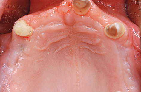
Fig 7-4n Thin mucosa and slight perforations over the implants.
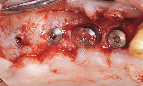
Fig 7-4o Distal implants overgrown with bone and peri-implantitis around the mesial implants.
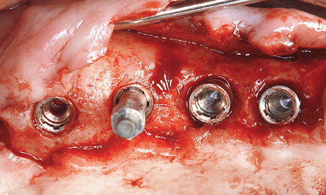
Fig 7-4p Measuring implant stability with resonance frequency analysis.
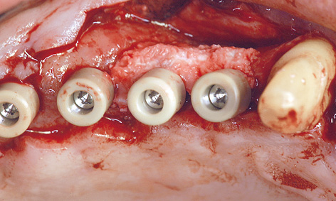
Fig 7-4q Augmentation of the defects at the time of exposure.
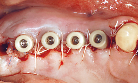
Fig 7-4r Widening the zone of attached gingiva.
Exposure in the maxilla
All the implants were exposed 7 months after implant placement in the maxilla. Although the patient had not been wearing a removable denture at the time, the mucosa above the implants appeared to be perforated already (Fig 7-4n). The consequences of a perforation with an inflammatory component can be seen in Figure 7-4o. Whereas the posterior implants were partly covered with bone, funnel-shaped defects were visible around the anterior ones. These defects had filled with granulation tissue, which had to be carefully removed (Fig 7-4p). During the exposure operation, the stability of the implants was measured with resonance frequency analysis (Osstell Mentor; Osstell). The values were good, with no marked differences: going from region 17 to 14, they were 77, 80, 75 and 78, respectively. After cleaning, the defects were filled with hydroxylapatite (Ostim; Heraeus Kulzer) and the healing abutments screwed into place (Fig 7-4q). The labial/buccal flap was adapted to the abutments and fixed into place with sutures (Fig 7-4r).
Note on split-thickness flaps and roll flaps
On the left side, a pedunculated subepithelial graft was taken from the palate. A deep incision was made obliquely to the palate (Fig 7-4s) and a split-thickness flap approximately 10 mm in depth was created (Fig 7-4t). Heavier bleeding from the palatine artery region is to be expected with this kind of deep dissection. The lower part of the flap was separated from the bone, together with the periosteum at a depth of about 7 to 10 mm and dissected away in a coronally directed way (Fig 7-4u). The two parts of the flap were cleanly separated over the implants (Fig 7-4v). The long labial/buccal flap was prepared for rolling (Fig 7-4w). The healing abutments were fitted onto the implants and the labial/buccal flap adapted to their surfaces in the form of a roll flap (Fig 7-4x) and fixed into place with sutures (Fig 7-4y). This would later result in a wide zone of attached gingiva on the labial/buccal side (Fig 7-4z).
All the implants in the maxilla had undergone osseointegration and were exposed using the technique for widening the zone of keratinized gingiva (Fig 7-4aa).
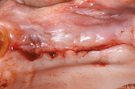
Fig 7-4s Incision for the pedunculated subepithelial graft.
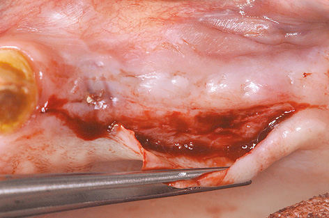
Fig 7-4t Creating the split-thickness flap.
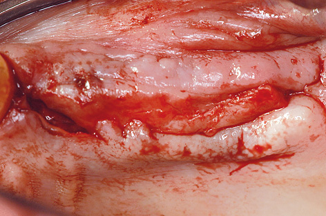
Fig 7-4u Separating the lower split-thickness flap with periosteum from the bone.
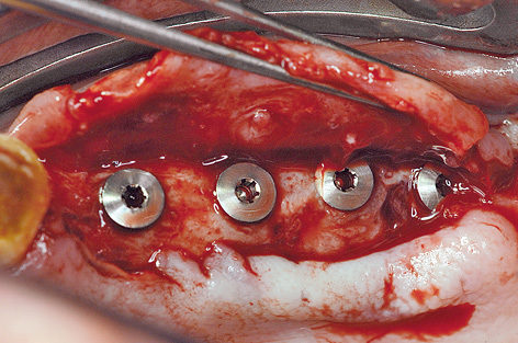
Fig 7-4v Dividing the flaps.
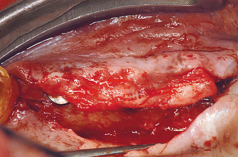
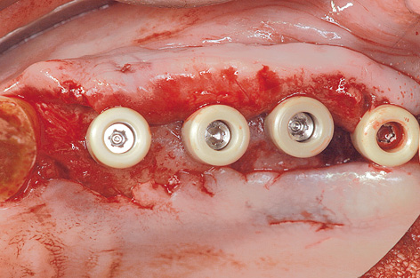
Fig 7-4x Healing abutments screwed into place to act as supports.
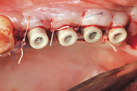
Fig 7-4y Fixing the flap into place with sutures.
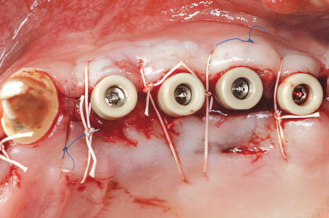
Fig 7-4z Widened the zone of attached gingiva.
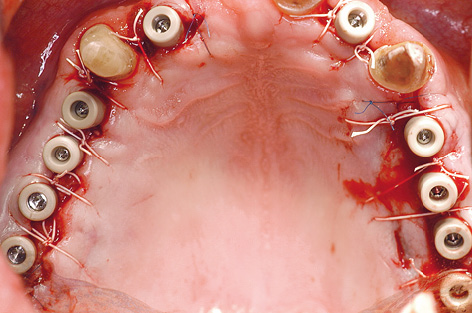
Fig 7-4aa Maxilla after the exposure.
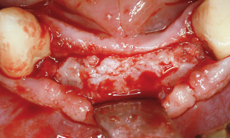
Fig 7-4bb More than successful augmentation in the anterior mandible.
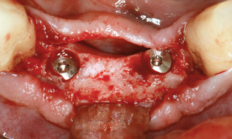
Fig 7-4cc Reaming the bone away from the implants.
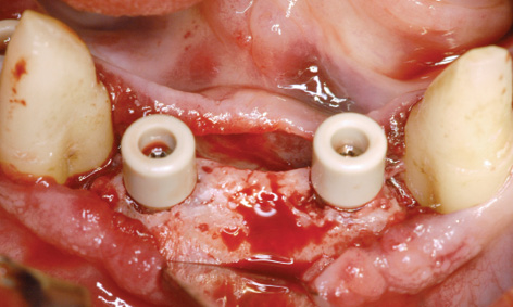
Fig 7-4dd Healing abutments screwed into place.
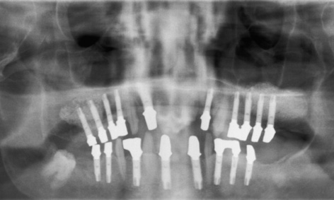
Fig 7-4ee Check panoramic radiograph with the abutments in place.
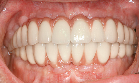
Fig 7-4ff Screw-retained, metal-ceramic fixed bridges in both jaws.
Exposure in the mandible
The eight implants in the mandible were also exposed during the same session, after a healing period of 15 months. The augmentation had been particularly successful in the anterior segment (see Fig 7-4d and 7-4bb). The implants were so overgrown with new bone that they had to be located first and the bone reamed away to expose them (Fig 7-4cc). When screwing on the healing abutments, care was needed to ensure that they were not collided with the bone margins at the sides (Fig 7-4dd).
Prosthetic restoration
Customized abutments were fabricated on all the implants and their fit checked with a panoramic radiograph (Fig 7-4ee). A horizontal, screw-retained attachment was incorporated into each quadrant to ensure secure fixation of the superstructure. All the implants in the maxilla and mandible were prosthetically loaded with metal-ceramic fixed restorations, divided at the midline (Fig 7-4ff). The four fixed bridges were screwed onto the implants, allowing the dentist to remove them easily at any time.
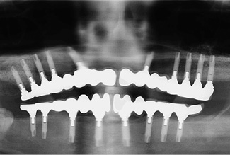
Fig 7-4gg Follow-up panoramic radiograph taken after 8 years.
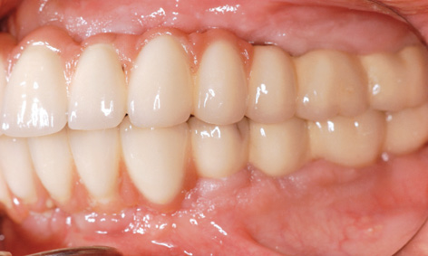
Fig 7-4hh Near-natural appearance of the restoration on the left side.
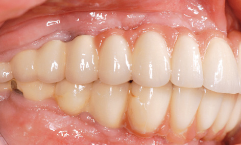
Fig 7-4ii Short implant crowns on the right side.
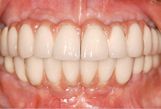
Fig 7-4jj Secondary diastema between the two fixed bridges in the maxilla.
Continued follow-up
The bone situation after 8 years appears to be stable on the panoramic radiograph (Fig 7-4gg). The volume gained with the sinus elevation appears to have changed little during this time. An incidental finding made on this occasion was that the screw of implant 27 was missing and that a gap had opened up there. The fixed restorations on the left side, in both jaws, look comparatively natural in the molar region (Fig 7-4hh). On the right side, the distance between the jaws is very small and the implant crowns appear correspondingly short (Fig 7-4ii). One facet has broken off on the mandibular side. The overall picture after 8 years is satisfactory, apart from an imminent (and necessary) professional cleaning session (Fig 7-4jj). It is interesting to note that a diastema has formed between the front teeth, which was not detectable at the time of fitting (see Fig 7-4ff).
Treatment course
- Dental treatment including extractions (2003)
- 2 months to bilateral sinus elevation and implant placement in the mandible
- 8 months to implant placement in the maxilla
- 7 months to exposure of all the implants
- 3 months to the final prosthetic loading
- 7 months to exposure of all the implants
Treatment
|
Surgery: |
Dr Christoph T. Sliwowski |
|
Prosthetics: |
Dr Michael Weber |
|
Dental technology: |
Horst Mosch |
Atypical treatment course – problematic baseline situation
Sinus elevation, subsequent implant placement without immediate prosthetic loading
Baseline situation
A 55-year-old man, who is a heavy smoker (20 to 30 cigarettes a day), was complaining of inadequate dental prostheses in his maxilla and mandible and wanted to know if a fixed restoration was an option (Fig 7-5a). Although his four mandibular incisors were still in relatively good condition, they stood in the way of a fixed restoration and needed to be extracted before implant placement (Fig 7-5b). The panoramic radiograph showed severely pneumatized maxillary sinuses on both sides, so that implant placement in the maxilla would not be possible without prior sinus elevation (Fig 7-5c). In this radiograph, the mandible appeared to be in very good condition; in particular, it was of sufficient height in the interforaminal region. The width of the residual ridge, however, was apparent only in the CBCT scan (Fig 7-5d). This showed it to be very narrow and that a reduction in the height of the residual ridge plus augmentation around the implants would be needed in addition to implant placement.
Diagnostic tools
- Clinical examination
- Panoramic radiograph
- CBCT
- SimPlant planning
- Dental cast analysis
Treatment plan
1.Bilateral sinus elevation and implant placement in the mandible
2.Implant placement in the maxilla
3.Exposure in the maxilla and mandible
4.Prosthetic loading
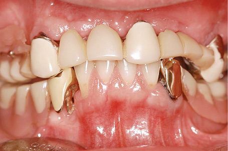
Fig 7-5a Inadequate dental prostheses before treatment.
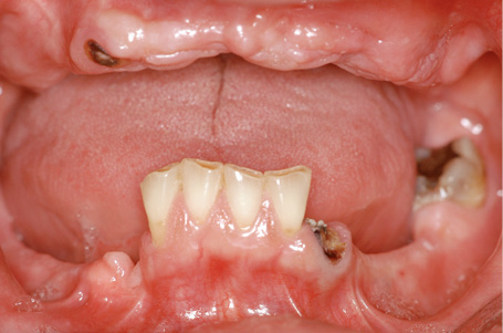
Fig 7-5b Clinical baseline situation.
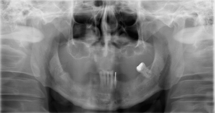
Fig 7-5c Panoramic radiograph before treatment.
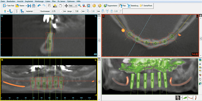
Fig 7-5d SimPlant planning for the mandible.
Implant placement in the mandible and sinus elevation
The operation took place under general anesthesia, starting with the mandible.
Attention: This sequence (mandible before maxilla) has been shown to be favorable for the following reason: when preparing bone beds for the implants in the mandible, it is often possible to collect larger quantities of bone chips with a filter, allowing them to be used for lateral augmentation of the maxilla. When doing so, it must be kept in mind that these bone chips are frequently contaminated with saliva and are not suitable for adding to the bone substitute (eg, Bio-Oss; Geistlich) used for sinus elevation, as they can infect it.
The anterior teeth and the remaining root of tooth 33 were extracted, the residual ridge was exposed and the top smoothed with a large reamer. Six implant beds were prepared in the interforaminal segment, and just as many 17-mm long implants were inserted. While the residual ridge was high, it was also very narrow, so that the screw threads of most of the implants were uncovered on the labial/buccal side (Fig 7-5e). The ridge was particularly narrow on the right side; for this reason, almost the full lengths of the implants in this area were exposed on the lingual sides (Fig 7-5f). Accordingly, it was not possible to harvest as much bone as usual in this case, and most of this bone was used up for the augmentation in the mandible. Immediate loading of the implants with an implant-supported provisional restoration had to be avoided. The augmentation was performed with the harvested bone chips and Bio-Oss. A BioGide (Geistlich) membrane 30 × 40 mm in size was used to cover the augmentation. Following saliva-proof suturing of the operation site, work began on the maxilla.
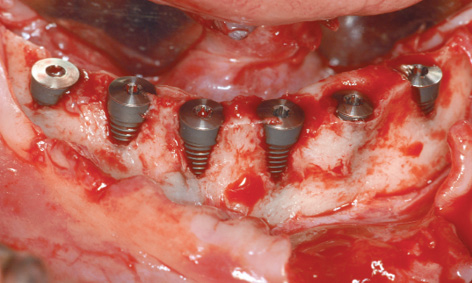
Fig 7-5e Visible screw threads on the labial/buccal side of almost all the implants.
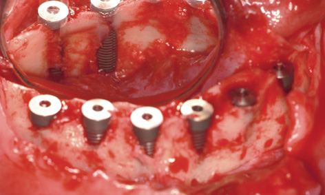
Fig 7-5f The screw threads on the lingual side are also exposed.
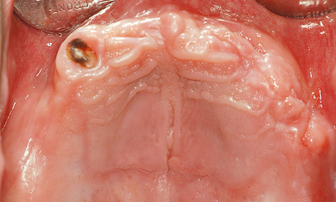
Fig 7-5g Maxilla before sinus elevation.
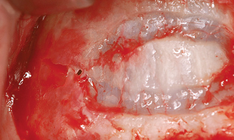
Fig 7-5h Perforation of the maxillary sinus mucosa during fenestration.
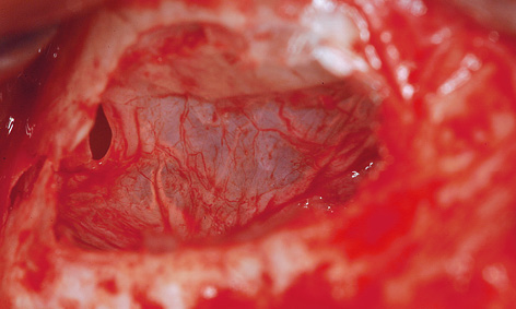
Fig 7-5i The mucosa has been carefully elevated.
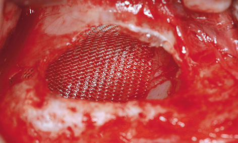
Fig 7-5j Sealing the perforation.
After infiltration anesthesia was induced, root 13 was extracted and the fenestration prepared for the sinus elevation on the right side (Fig 7-5g). The patient is of very slender, almost asthenic build, and has a bone structure to match. The outer wall of the maxillary sinus was so thin that the periosteal elevator fell into the maxillary sinus during the dissection (Fig 7-5h), causing direct perforation of the sinus mucosa. Extremely careful dissection was needed to prevent the perforation from spreading any further (Fig 7-5i). The perforation was covered with Vicryl mesh (Ethicon), to stop the graft material from escaping into the maxillary sinus (Fig 7-5j). The prepared cavity was filled with Bio-Oss (Fig 7-5k) and the window closed with a membrane. The left maxillary sinus was divided by a septum, making dissection more difficult (Fig 7-5l). A perforation occurred despite the increased care exercised while detaching the membrane (Fig 7-5m). However, the perforation was kept within limits, allowing the mucous membrane to be elevated over the septum (Fig 7-5n). After the augmentation material was introduced, the window was sealed with a Bio-Gide membrane and the operation site sutured closed. A healing period of 9 months was scheduled. The postoperative panoramic radiograph clearly shows the distribution of the implants in the mandible, in contrast to the sinus elevation in the maxilla (Fig 7-5o). The patient wanted to keep tooth 38 at any cost.
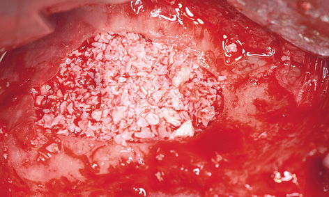
Fig 7-5k Filling the cavity.
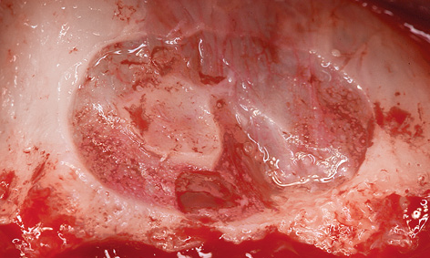
Fig 7-5l Fenestration of the left maxillary sinus.
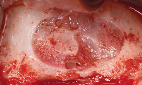
Fig 7-5m Perforation of the maxillary sinus mucosa at the septum.
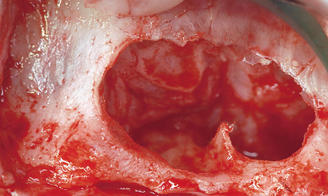
Fig 7-5n The mucosa has been lifted.
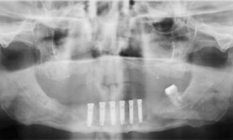
Fig 7-5o Panoramic radiograph after the operation.
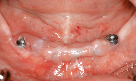
Fig 7-5p Exposed distal implants in the mandible.
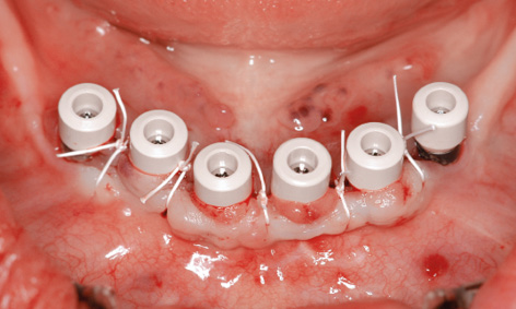
Fig 7-5q Healing abutments screwed into place.
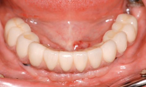
Fig 7-5r Screw-retained cantilever bridge as the definitive restoration in the mandible.
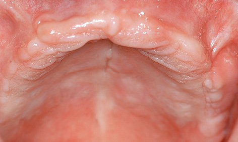
Fig 7-5s Maxilla before implant placement.
< div class='tao-gold-member'>
Stay updated, free dental videos. Join our Telegram channel
VIDEdental - Online dental courses


