Introduction
When mini-implants fail during orthodontic treatment, there is a need to have a backup plan to either replace the failed implant in the adjacent interradicular area or wait for the bone to heal before replacing the mini-implant. We propose a novel way to overcome this problem by replacement with a miniplate so as not to interrupt treatment or prolong treatment time.
Methods
The indications, advantages, efficacy, and procedures for switching from a mini-implant to a miniplate are discussed. Two patients who required replacement of failed mini-implants are presented. In the first patient, because of the proximity of the buccal vestibule to the mini-implant, it was decided to replace the failed mini-implant by an I-shaped C-tube miniplate. In the second patient, radiolucencies were found around the failed mini-implants, making the adjacent alveolar bone unavailable for immediate placement of another mini-implant. In addition, the maxillary sinus pneumatization was expanded deeply into the interradicular spaces; this further mandated an alternative placement site. One failed mini-implant was examined under a scanning electron microscope for bone attachment.
Results
Treatment was completed in both patients after replacement with miniplates without interrupting the treatment mechanics or prolonging the treatments. Examination under the scanning electron microscope showed partial bone growth into the coating pores and titanium substrate interface even after thorough cleaning and sterilization.
Conclusions
Replacement with a miniplate is a viable solution for failed mini-implants during orthodontic treatment. The results from microscopic evaluation of the failed mini-implant suggest that stringent guidelines are needed for recycling used mini-implants.
The most commonly used temporary skeletal anchorage device (TSAD) is a mini-implant because of its compact size for the interradicular space, low cost, and various screw-head designs favorable for orthodontic archwire engagement. The success rates of these mini-implants and screws, however, vary from 75.2% to 93.6%. When mini-implants loosen during active orthodontic treatment, the best recommended alternative is to immediately replace them at adjacent interradicular spaces with better alveolar bone mass. The unexpected loosening of mini-implants at any stage of treatment can easily jeopardize the entire original orthodontic treatment plan, especially when the treatment biomechanics require continuous anchorage support.
To date, there are no recommendations in the literature on how to sustain the original treatment mechanics when the conditions of the adjacent areas do not guarantee better stability after replacement of failed mini-implants. These preexisting anatomic conditions might include severe pneumatization of the maxillary sinus, extremely narrow interradicular space, insufficient amount of attached gingiva, unfavorable frenal attachment, or abnormal distribution of nerve and blood vessels.
Since contemporary orthodontic treatment planning now commonly includes many types of mini-implants as critical components of biomechanics for a patient’s successful orthodontic treatment, the plan should also incorporate a backup plan that would allow the clinician to continue the original treatment mechanics with no delay. This will enable clinicians to use mini-implants in any situation and be confident of the clinical outcome, eventually leading to more extensive and universal uses of TSADs in orthodontics in the long term.
This report suggests a novel way of ensuring the continuity of treatment mechanics despite the failure of a mini-implant during comprehensive orthodontic treatment. The case reports also emphasize the importance of restricting the reuse of mini-implants to the same patient based on the scanning electron microscope (SEM) evaluation of the failed mini-implant’s surface.
Clinical applications
Patient 1
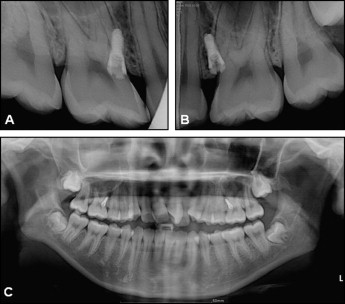
A 14-year-old girl with a chief complaint of bimaxillary protrusion agreed to an orthodontic treatment plan based on the philosophy of biocreative therapy. The treatment goals were to perform en-masse retraction of the maxillary anterior teeth and reduce her facial convexity while maintaining the preexisting Class I posterior occlusal relationship ( Fig 1 ). Therefore, a 2-component orthodontic mini-implant (C-implant, Cimplant Co, Seoul, Korea) of 1.8 mm in diameter and 8.5 mm in length was placed bilaterally between the maxillary second premolar and the first molar. This mini-implant served as an independent orthodontic anchor and excluded the molars from use as anchorage. During the fourth week of active en-masse retraction, the mini-implant on the right side loosened ( Figs 1 , A , and 2 ), and the active en-masse retraction could no longer be continued against the loose mini-implant. At this stage, there was still significant extraction space, and the treatment was far from reaching the initial goal.
To sustain the initially planned biocreative therapy (C-therapy) mechanics without delay and to avoid occlusal canting that can result from bilateral en-masse retraction with different points of force application relative to the center of resistance of the retracted segment, it was desirable to maintain the point of force application of the orthodontic anchor at the same place. In addition, the proximity of the patient’s buccal vestibule to the mini-implant site indicated that the immediate relocation of the loose mini-implant farther apically would not be desirable. More importantly, there was no guarantee of stability of the replanted mini-implant at the same location even with 1 or 2 months of healing after removal of the loose mini-implant.
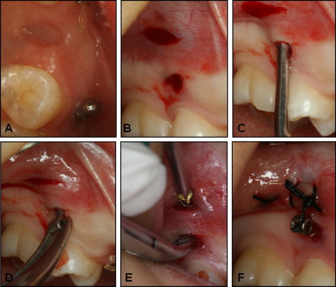
With all these factors taken into consideration, we decided to remove the loose mini-implant and place a different type of temporary skeletal anchorage device at the same patient appointment. The treatment of choice was an I-shaped miniplate with a tube-shaped head (C-tube, Jin Biomed Co., Bucheon, Korea) ( Fig 3 ). This I-shaped C-tube is a titanium miniplate with 2 anchoring holes and a .0036-in diameter tube-shaped head serving as the point of orthodontic force application. This modification accommodates the same biomechanics for the C-therapy and also achieves much higher stability during active en-masse retraction. The details of the switching procedure are as follows.
The failed mini-implant was removed with a screwdriver or a Weingart plier. After local anesthesia was applied submucosally around the mini-implant screw-body area and below its mucogingival junction, the screw body was taken out with a hand screwdriver by rotating it counterclockwise. The hole left after the screw body was removed served as the entry point of the I-shaped C-tube miniplate. Then a 3-mm long horizontal incision was made with a number 15 surgical scalpel approximately 2 mm apical to the screw-body removal site ( Fig 4 , A and B ), and this incision was the access point for securing the miniplate with miniplate anchoring screws (MPAS). The alveolar bone under the 2-mm wide mucosal-periosteal tissue needs to be properly exposed by gross dissection with a periosteal elevator ( Fig 4 , C ). The side of the miniplate with the anchoring holes was placed through the mucosal hole left after the screw body was removed, leaving the C-tube (the head part of the miniplate) exposed to the oral cavity at the same location as the failed mini-implant ( Fig 4 , D ). Once the miniplate was placed under the lifted 2-mm wide mucogingival-periosteal tissue, then the anchoring side of the miniplate needed to be better adapted to the contour of the exposed bony surface by molding the miniplate against the bony surface with direct pressure from the dull end of a periosteal elevator. When the anchoring side of the miniplate was adequately adapted, it was fixed into place with 2 self-drilling MPAS (diameter, 1.5 mm; length, 4 mm) ( Fig 4 , E ). A single stitch with 4-0 silk on the incision was used for placement of the MPAS to facilitate soft-tissue closure and healing ( Fig 4 , F ). Analgesics or antibiotics can be prescribed, but most over-the-counter painkiller medications should be sufficient to alleviate the postsurgical discomfort. With adequate oral hygiene and the use of chlorhexidine gluconate for a week after the procedure, this small incision site tends to heal quickly with no subsequent medical complications. The suture material is removed a week after this procedure.
After switching from the loose mini-implant to an I-shaped miniplate on the same day, the full retraction force used to achieve active en-masse retraction was loaded on the miniplate on the right side and on the existing mini-implant on the left side ( Fig 5 ). The procedure for switching from a loose mini-implant to an I-shaped miniplate is simple enough for an orthodontist who is already familiar with the placement of mini-implants in interradicular spaces.
When the miniplate was no longer needed for orthodontic treatment, a single small vertical incision was made above the miniplate restricted to the area of the 2 MPAS, providing easy access to the MPAS. After the 2 MPAS were unscrewed, the miniplate could be removed by pulling it out through the hole where the C-tube was exposed to the oral cavity. This removal procedure can be performed by using slight local anesthesia, and minimum suture was required after it was removed. Again, with adequate oral hygiene and the use of chlorhexidine gluconate for a few days after this procedure, the small incision site tends to heal quickly with no further medical complications.
Patient 2
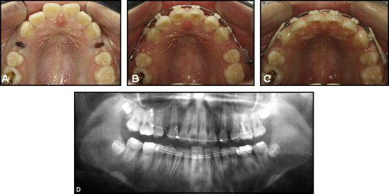
A 16-year-old girl with a Class I malocclusion and bimaxillary dentoalveolar protrusion was planned for extraction of the maxillary first premolars and en-masse retraction of the maxillary incisors with biocreative therapy. Figure 6 shows the placement of mini-implants between the maxillary left and right second premolars and the first molars. The mini-implants were left unloaded for 4 weeks to allow partial osseointegration and secure their stability. Meanwhile, the patient was referred to an oral surgery for extraction of the maxillary first premolars. The patient returned 4 weeks after the extractions, and both mini-implants were found to be loose with obvious radiolucencies around them, making the adjacent alveolar bone unavailable for immediate placement of another mini-implant. In addition, the maxillary sinus pneumatization was expanded deeply into the interradicular spaces; this further mandated a higher level of anchoring system to ensure the stability of the alternative TSAD. It was decided to switch the failed mini-implants with a cross-shaped miniplate with a tube-shaped head (C-Tube, KLS Martin, Tuttlingen, Germany) with 4 MPAS placement holes (instead of the I-shaped miniplate with only 2 MPAS). The switching procedure was similar to that described previously, except that the tube-shaped head was placed through the incision apical to the mini-implant removal site, sliding down under the lifted mucoperiosteal tissue and exposed to the oral cavity through the hole left after the mini-implant was removed ( Fig 7 ). The cross-shaped anchoring side of the miniplate was also placed through the same incision. After the miniplate was placed, it was passively adapted to the contour of the lateral wall of the maxillary sinus before placing the first MPAS. The dull end of a periodontal elevator was useful for this adaptation procedure. Although placement with 4 MPAS is ideal, 3 MPAS should be sufficient to fully secure the stability of the miniplate if the maxillary sinus pneumatization seems excessively large. After its placement, the miniplate was immediately loaded for the en-masse retraction of the maxillary anterior teeth ( Fig 8 ).