Introduction
The purpose of this study was to develop a new methodology to visualize in 3 dimensions whole teeth, including the roots, at any moment during orthodontic treatment without the need for multiple cone-beam computed tomography (CBCT) scans.
Methods
An extraoral typodont model was created using extracted teeth placed in a wax base. These teeth were arranged to represent a typical malocclusion. Initial records of the malocclusion, including CBCT and intraoral surface scans, were taken. Threshold segmentation of the CBCT was performed to generate a 3-dimensional virtual model. This model and the intraoral surface scan model were superimposed to generate a complete set of digital composite teeth composed of high-resolution surface scan crowns sutured to the CBCT roots. These composite teeth were individually isolated from their respective arches for single-tooth manipulations. Orthodontic treatment for the malocclusion typodont model was performed, and posttreatment intraoral surface scans before and after bracket removal were taken. A CBCT scan after bracket removal was also obtained. The isolated composite teeth were individually superimposed onto the posttreatment surface scan, creating the expected root position setup. To validate this setup, it was compared with the posttreatment CBCT scan, which showed the true positions of the roots. Color displacement maps were generated to confirm accurate crown superimpositions and to measure the discrepancies between the expected and the true root positions.
Results
Color displacement maps through crown superimpositions showed differences between the expected and true root positions of 0.1678 ± 0.3178 mm for the maxillary teeth and 0.1140 ± 0.1587 mm for the mandibular teeth with brackets. Once the brackets were removed, differences of 0.1634 ± 0.3204 mm for the maxillary teeth and 0.0902 ± 0.2505 mm for the mandibular teeth were found.
Conclusions
A new reliable approach was demonstrated in an ex-vivo typdont model to have the potential to track the 3-dimensional positions of whole teeth including the roots, with only the initial CBCT scan and consecutive intraoral scans. Since the presence of brackets in the intraoral scan had a minimal influence in the analysis, this method can be applied at any stage of orthodontic treatment.
In orthodontic treatment, various orthodontic appliances are used to move teeth from malocclusion to a functional and stable occlusion with the teeth in their proper relationships to one another as well as in harmony with the maxillofacial hard and soft tissues. The 6 characteristics or keys that describe tooth locations in 3-dimensional (3D) space and are necessary for successful orthodontic treatment outcomes were defined by Andrews in his study of the crowns of 120 sets of stone models of nonorthodontic patients with ideal occlusions. Andrews later developed the treatment goal concept in addition to the initial preadjusted orthodontic appliances that contained built-in dimensional and angular information for every tooth. These advancements resulted in less wire bending necessary for successful orthodontic treatment. Current preadjusted appliances are mostly derived from Andrews’ original straight-wire appliances designed based on the crown norms that he had measured. These preadjusted appliances allow the orthodontist to treat patients with more efficiency and improve the quality of orthodontic finishing. However, because of inaccuracies in bracket positioning during the initial bonding process and variations in tooth anatomies and bracket designs, Andrews’ 6 keys are difficult to achieve for even experienced orthodontists. Furthermore, because Andrews focused solely on the crown and not on the entire tooth, root position at the end of the treatment might be compromised. Thus, it is common to have improper root placement throughout orthodontic treatment, resulting in the need to visualize the roots frequently with radiographs to make the necessary corrections.
Traditionally, monitoring and finalizing the root positions has been performed using panoramic x-rays at the initial, progress, and finishing stages of orthodontic treatment. A 2008 survey showed that 67.4% and 80.1% of American orthodontists take progress and posttreatment panoramic radiographs, respectively. However, many studies have indicated that panoramic x-rays do not accurately reflect the true root positions, especially of the canines and first premolars, as a result of distortions mainly due to the x-ray beam’s not being orthogonal to the target teeth. Therefore, a new method to accurately visualize root positions at different stages in orthodontic treatment is needed.
In recent years, the development and use of cone-beam computed tomography (CBCT) has allowed for accurate visualization of the roots of teeth in 3 dimensions. However, a CBCT scan uses significantly more radiation than does a panoramic radiograph, so multiple CBCT scans would not be suggested clinically. An imaging technique that can be performed many times during orthodontic treatment without radiation is a digital intraoral surface scan. This technique can accurately display crowns with high resolution, but it cannot show the roots. Since neither CBCT nor digital intraoral surface scans can safely and accurately visualize root positions at different stages of orthodontic treatment, root tracking might be possible with a combination of these 2 imaging techniques. Therefore, the aim of this study was to devise a new methodology that combines the pretreatment CBCT scan with digital intraoral surface scans, resulting in safe and accurate root position assessment in 3 dimensions throughout orthodontic treatment.
Material and methods
An extraoral “typodont” model of extracted teeth with intact roots arranged in an ideal occlusion and placed in pink dental wax was created, and then these teeth were rearranged in a typical malocclusion ( Fig 1 , A ). Initial records including CBCT and direct intraoral surface scans were taken. The typodont was scanned with a Galileos Comfort 3D scanner (Sirona, Charlotte, NC), set at 85 kVp, 7 mA, 14-second scan time, 15-cm spherical field of view size, and 0.15-mm voxel dimension. The typodont’s digital imaging and communications in medicine (DICOM) data obtained from the CBCT scan were imported into Mimics (version 15.0; Materialise, Leuven, Belgium). A threshold segmentation of 2224 to 4095 gray levels was applied to the DICOM data, resulting in the generation of 3D virtual surface models of the maxillary and mandibular dental arches that include whole teeth including the roots ( Fig 2 , A ). These 2 arches were imported into 3-matic (version 7.0; Materialise) in which each tooth is individually isolated from its respective arch into its own whole tooth part for single-tooth manipulation ( Fig 2 , B ).
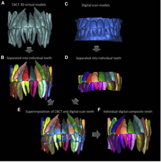
An iTero intraoral scanner (Align Technology, San Jose, Calif) was used to digitally scan the crowns of the typodont teeth, resulting in stereolithography files of the maxillary and mandibular arches in high resolution ( Fig 2 , C ). The stereolithography files of these arches were imported into the 3-matic, in which the crowns of the iTero arches were also individually isolated into their own crown parts for single-crown manipulation ( Fig 2 , D ). The CBCT isolated tooth parts were then superimposed onto their respective iTero isolated crown parts ( Fig 2 , E ). Since the iTero scans do not capture the roots, the CBCT roots were removed before generating color displacement maps with the 3-matic to confirm accurate superimpositions between the CBCT and the iTero crowns. Color maps showed the displacement between the closest points between 2 compared parts: the CBCT and iTero crowns. The CBCT and iTero crowns are composed of approximately 60,000 and 300,000 points, respectively, and the color map generated showed the minimum displacement between all of these points. In addition, the 3-matic outputs the mean and maximum displacements as well as the standard deviation measured in the color map analysis. The 3-matic also outputs a histogram that recorded all displacements between the points. After validation of accurate superimposition using a color map, the crowns of the low-resolution CBCT isolated teeth were removed, and the high-resolution iTero crowns were sutured onto the CBCT roots, creating individual digital “composite teeth” ( Fig 2 , F ).
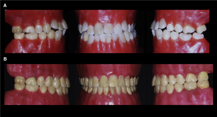
Orthodontic treatment was simulated on this extraoral typodont model by an experienced orthodontist (H.T.). A complete set of brackets was bonded, and a 0.014-in nickel-titanium archwire was tied to these brackets. The typodont was submerged into a hot-water bath at 125°F for 30 minutes. In hot water, the pink dental wax softens, allowing for accelerated tooth movement. After expression of the archwire, the typodont was quenched in cold water to stop the tooth movement. This procedure was repeated using consecutive archwires (0.016-in nickel-titanium, 0.016 × 0.022-in nickel-titanium, and 0.016 × 0.022-in stainless steel) until treatment was complete ( Fig 1 , B ). This simulated orthodontic treatment was completed within hours, in contrast to live orthodontic treatment, which requires many months to several years to finish.
After the orthodontic treatment, intraoral scans were taken before and after bracket removal of the posttreatment typodont model, hence the bracketed and nonbracketed crowns. A posttreatment CBCT image was also taken after bracket removal for validation. The following methodology was separately used on the bracketed and nonbracketed posttreatment intraoral scans to examine whether the presence of brackets affects the accuracy of the analysis. Threshold segmentation of the posttreatment CBCT scan at 2224 to 4095 gray levels and the stereolithography file from the intraoral scans were obtained and imported into the 3-matic. The crowns of the isolated individual composite teeth created previously were superimposed independently onto the iTero digital scans of the posttreatment bracketed and nonbracketed crowns. Since these composite teeth also contained the root information, this crown superimposition resulted in the roots of the composite teeth being placed in the “expected root position” setup ( Fig 3 , A ). The posttreatment expected root position setup was compared with the true root position, which was recorded with the posttreatment CBCT virtual model. This posttreatment CBCT virtual model was also superimposed, but as 1 unit, onto the posttreatment iTero bracketed or nonbracketed crowns with which the expected root position model was currently superimposed ( Fig 3 , B ). After removal of the iTero scan, the expected root position setup and the posttreatment CBCT virtual model have been indirectly superimposed, allowing comparisons ( Fig 3 , C ).
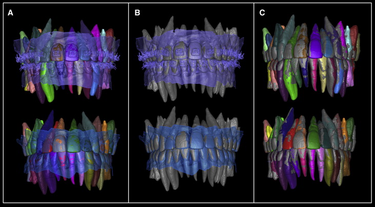
Next, the composite teeth of the expected root position setup and the CBCT virtual model teeth were cut at the cementoenamel junction, isolating the crowns and roots from each other. A color map was created that measured the displacements between the isolated crowns of the expected root position setup and the posttreatment CBCT virtual model to verify accurate superimpositions. A color map was also generated for the expected root positions and the posttreatment CBCT virtual models to measure the differences between the expected and true root positions.
Results
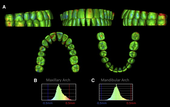
Color maps for the superimpositions between the CBCT virtual models and the iTero crowns displayed 3 colors: green, blue, and red ( Fig 4 ). Changes within a 0.5-mm range are shown as green, inward movement greater than 0.5 mm of the iTero crowns compared with the CBCT crowns is represented as blue, and outward movement greater than 0.5 mm is red. The maxillary and mandibular CBCT and iTero crowns were found to have differences of 0.034 ± 0.148 mm and 0.004 ± 0.147 mm, respectively. The maximum displacements between the CBCT and the iTero crowns for the maxillary and mandibular teeth were 0.824 and 0.913 mm, respectively ( Table I ).
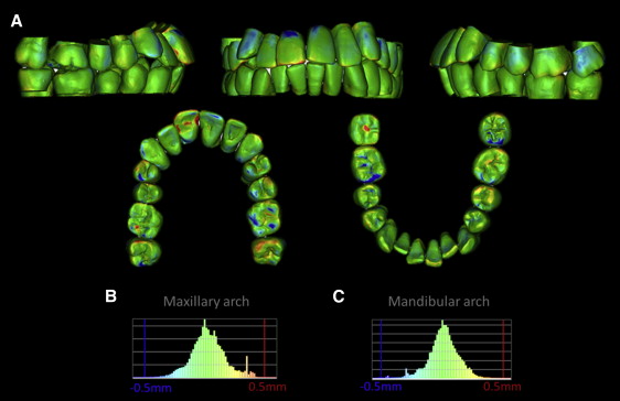
| Crown analysis type | Mean displacement (mm) | SD (mm) | Minimum displacement (mm) | Maximum displacement (mm) |
|---|---|---|---|---|
| iTero vs CBCT (pretreatment) | ||||
| Maxillary crowns | 0.034 | 0.148 | 0.000 | 0.824 |
| Mandibular crowns | 0.004 | 0.147 | 0.000 | 0.913 |
| ERP setup vs CBCT (posttreatment with brackets) | ||||
| Maxillary crowns | 0.062 | 0.202 | 0.000 | 1.421 |
| Mandibular crowns | 0.007 | 0.144 | 0.000 | 1.185 |
| ERP setup vs CBCT (posttreatment without brackets) | ||||
| Maxillary crowns | 0.065 | 0.197 | 0.000 | 1.471 |
| Mandibular crowns | 0.006 | 0.135 | 0.000 | 0.874 |
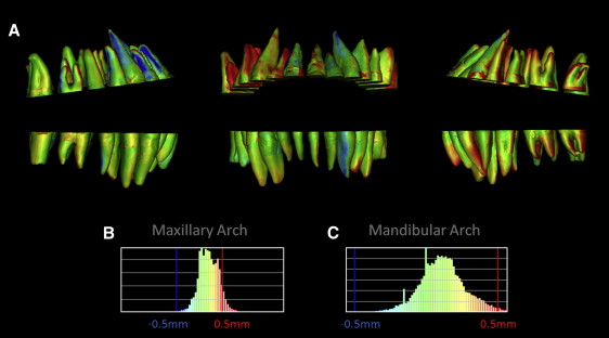
Color mapping from indirect superimposition of the expected root position setup crowns with the posttreatment CBCT crowns with iTero-scanned bracketed crowns showed maxillary displacements of 0.062 ± 0.202 mm with a maximum of 1.421 mm, and mandibular displacements of 0.007 ± 0.144 mm with a maximum of 1.185 mm ( Fig 5 , Table I ). Color mapping of the roots showed maxillary displacements of 0.168 ± 0.319 mm with a maximum of 1.859 mm, and mandibular displacements of 0.114 ± 0.159 mm with a maximum of 0.827 mm ( Fig 6 , Table II ).