INTRODUCTION
• Metals Used for Manufacturing Cutting Instruments
• Heat Treatment of Materials
CLASSIFICATION OF HAND CUTTING
INSTRUMENTS
• Classification Given by GV Black
• Classification Given by Marzouck
• Nomenclature for the Instruments
PARTS OF HAND CUTTING INSTRUMENTS
• Handle or Shaft
• Shank
• Blade or Nib
• Instrument Formula
• Bevels in Cutting Instruments
• Instrument Motions
EXPLORING INSTRUMENTS
• Mouth Mirrors
• Explorer
Tweezers
• Periodontal Probes
HAND CUTTING INSTRUMENTS
• Instrument Families
• Chisels
• Angle Former
• Cleiod-discoid
• Hatchet
• Spoon Excavator
• Gingival Margin Trimmer (GMT)
RESTORATION INSTRUMENTS
• Cement Spatulas
• Plastic Filling Instrument
• Condensers
• Amalgam Carriers
• Carvers
• Burnisher
• Composite Resin Instruments
INSTRUMENT GRASPS
• Modified Pen Grasp
• Inverted Pen Grasp
• Palm and Thumb Grasp
• Modified Palm and Thumb Grasp
FINGER RESTS
SHARPENING OF HAND INSTRUMENTS
• Goals of Sharpening
• Advantages of Sharp Instruments
• Principles of Sharpening
• Devices Used for Sharpening
• Guidelines for Sharpening Operative Instruments
ROTARY CUTTING INSTRUMENTS
• Types of Rotary Cutting
• Handpieces
• Dental Burs
• Factors Affecting Cutting Efficiency of Bur
RECENT ADVANCES IN ROTARY INSTRUMENTS
• Fiberoptic Handpiece
Smart Prep Burs
• Chemical Vapor Deposition (CVD) Diamond Burs
• Fissurotomy Burs
ABRASIVE INSTRUMENTS
• Diamond Abrasive Instruments
• Other Abrasive Instruments
• Finishing and Polishing Instruments
• Advantages of Bur Cutting
• Disadvantages
ULTRASONIC INSTRUMENTS
HAZARDS AND PRECAUTIONS WITH ULTRASPEED CUTTING INSTRUMENTS
• Pulpal Damage
Damage to Soft Tissue
• Damage to Ear
• Inhalation Problems
• Eye Injuries
INTRODUCTION
For preparation of tooth, cutting the tooth tissue and for other operative procedures wide range of specific instruments is required which can be hand or/and rotary. Rotary instruments help in gross cutting and final refining of the preparation whereas hand instruments are used for examination, producing minor details of the tooth preparation and for insertion, compaction and finishing of the restoration. One must be able to use both hand and rotary instruments judiciously so as to perform the operative procedures accurately. In this chapter we will discuss different types of instruments and instrumentation techniques used in operative dentistry.
In Lilian Lindsay’s English translation of 1946, it has been shown that most preparation was carried out by hand instruments. Fauchard advocated the use of the manually operated bow drill, an unwieldy device widely used in the early 18th century and adapted by dentists from the workshops of jewellers, silversmiths and ivory turners. George Greenwood, modified spinning wheel for use as footoperated dental engine in 1790. The first commercially manufactured footpowered engine was patented by Morrison in 1871.
Black described hand instruments as chisels, hatchets, hoes, excavators and margin trimmers-terms which might have been taken from wood working and gardening.
Metals Used for Manufacturing Cutting Instruments
Carbon steel or stainless steel are most commonly used for manufacturing of cutting instruments.
The Carbon Steel
Carbon steel alloy contains 0.5 to 1.5% carbon in iron. Instruments made from carbon steel are known for their hardness and sharpness. But disadvantages with these instruments are their susceptibility to corrosion and the fracture of instrument if dropped. They are of two types:
1. Soft steel: It contains < 0.5% carbon
2. Hard steel: It contains 0.5-1.5% carbon
Stainless Steel
Stainless steel alloy contains 72 to 85% iron, 15 to 25% chromium and 1 to 2% carbon. Instruments made from stainless steel remain shiny bright because of deposition of chromium oxide layer on the surface of the metal and chromium reduces the tendency to tarnish and corrosion. Problem with stainless steel instruments is that they tend to lose their sharpness with repeated use, so they need to sharpened again and again.
Heat Treatment of Materials
For gaining maximum benefits from instruments made from carbon or stainless steel, they are subjected to two heat treatments-hardening and tempering heat treatment.
• Hardeningheat treatment: In this, instrument is heated to 815°C in oxygen free environment and then quenched in a solution of oil. By hardening treatment, the alloy becomes brittle.
• Tempering heat treatment: In this, instrument is heated at 176°C and then quenched in solutions of oil, acid or mercury. Tempering heat treatment is done to relieve the strains and increase the toughness of alloy.
CLASSIFICATION OF HAND CUTTING INSTRUMENTS
Classification Given by GV Black
This classification is based according to use of the instrument.
1. Cutting instruments

2. Condensing instruments
Pluggers
• Hand
0 Mechanical
3. Plastic instruments
• Plastic filling instrument
• Cement carriers
• Carvers
• Burnishers
• Spatulas
4. Finishing and polishing instruments

5. Isolation instruments
• Rubber dam frame clamps, forceps and punch
• Saliva ejector
• Cotton roll holder
• Evacuating tips and equipment
6. Miscellaneous instruments
• Mouth mirrors
• Explorers
• Probes
• Scissors
• Pliers
• Others
Classification Given by Marzouck
This classification is based upon different procedures performed by different instruments.
1. Exploring instruments
• Tweezers/cotton pliers
• Retractors: Mouth mirror, blunt bladed restoring instruments, plastic instruments, tongue depressors
• Probes/Explorers: Straight, right angled, arch explorer, interproximal explorer.
• Separators
2. Instruments for tooth structure removal
a. Hand cutting instruments
• Excavators: Hatchet, hoes, spoon, discoid, cleoid, angle formers.
• Chisels: Straight, monoangle, biangle and triple angle.
• Spec] al forms ofchisel: Enamel hatchets, gingival marginal trimmers, Wedelstaedt chisel, offset hatchets, triangular chisel and hoe chisel.
b. Rotary cutting and abrasive instruments
• Handpieces
• Burs
• Ultrasonic instruments
3. Restoring instruments
• Mixinginstruments: Stainless steel or plastic spatulas
0 Plastic instruments
• Condensing instruments: Rounded, triangular, diamond, or parallelogram condensers.
• Burnishing instruments: Ball/egg/conical-shaped burnishers
• Carvers: Hollenback’s discoid and cleoid, diamond shaped carvers
• Files: Hatchet/parallelogram-shaped
• Knives: Bard parker knife and Stein’s knife.
4. Finishing and polishing instruments: Burs, stones, brushes, rubber (wheel, cups or cones), cloth or felt.
Nomenclature for the Instruments
Dr GV Black has given a way to describe instruments for their easier identification similar to biological classification.
1. Order: Function or purpose of the instrument, e.g. excavator, condenser.
2. Suborder: Position, mode or manner of use, e.g. push, pull.
3. Class: Design or form of the working end, e.g. hatchet, spoon excavator.
4. Subclass: Shape of the shank, e.g. binangle, contra-angle.
These names are combined to give a complete description of the instrument. Naming of an instrument generally moves from 4 to 1. Sometimes, the suborder is omitted due to variable and nonspecific use of the instrument. For example, the instrument will be named according to the classification as biangle enamel hatchet or biangle spoon excavator.
PARTS OF HAND CUTTING INSTRUMENTS
Though there is great variation among hand cutting instruments, they have certain design features in common.
Each hand instrument is composed of three parts (Figs 5.1A and B)
1. Handle or shaft
2. Shank
3. Blade or nib
Handle or Shaft
The handle is used to hold the instrument. The handle can be small, medium or large, smooth or serrated for better grasping and developing pressure (Figs 5.2A to Q. Earlier, instruments had handles of quite large diameter and were to be grasped in the palm of the hand.
Nowadays, instrument handles are smaller in diameter for ease of their use. On the handle, there are two numbers; one is the instrument formula, which describes the dimensions and angulation of the instrument, the other number is the manufacturer’s number which is used for ordering purposes.
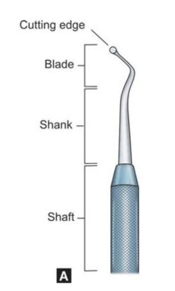
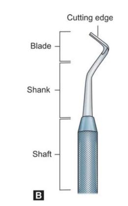
Figs 5.1A and B: Parts of a hand instrument
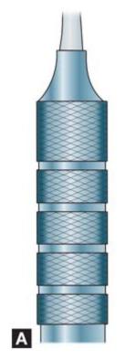
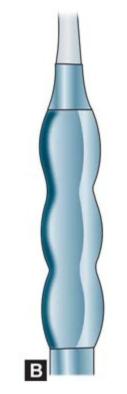
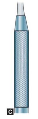
Figs 5.2A to C: Different designs of instrument handle for better grasping
Shank
Shank connects the handle to the blade. It tapers from the handle down to the blade and is normally smooth, round or tapered. The shank may be straight or angled.
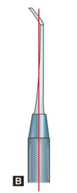
Based on number of shank angles (Figs 5.3A to D), instruments can be classified as:
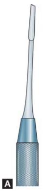
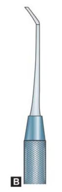
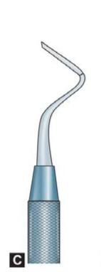
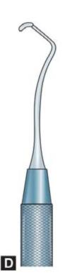
Figs 5.3A to D: Instruments with different shank angles
1. Straight: Shank having no angle.
2. Monoangle: Shank having one angle.
3. Mangle: Shank having two angles.
4. Triple angle: Shank having three angles.
The angulation of instrument is provided for access and stability. Closer the working point to the long axis of the handle, better will be the control on it. For better control, the working point should be preferably within 3 mm of the center of the long axis of the handle (Figs 5.4A and B).
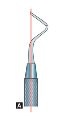
Figs 5.4A and B: Balancing of instrument (A) Working end of instrument lies within 2-3 mm to long axis of handle, this provides balancing, (B) Working end is away from long axis of handle, this is not balanced
Blade or Nib
The blade is the last section. It is the working part of the instrument. It is connected to the handle by the shank. For non-cutting instruments, the working part is termed the nib and is used to place, adapt and condense the materials in the prepared tooth. Depending on the materials being used, the surface of the nib may be plain or serrated. To cleave and smoothen the enamel and dentin, the working point of the instrument is beveled to create the cutting edge. If instrument has blade on both the ends of the handle, it is known as “double-ended” instrument. In such cases, one end is for the left side and other for the right.
In some instruments, there are three bevels. Two are on the side and one is at the end. The edge on the end is called the primary cutting edge and the edges on the sides are called the secondary cutting edges.
Instrument Formula
GV Black established an instrument formula for describing dimensions of blade, nib or head of instrument and angles present in shank of the instrument (Fig. 5.5). The formula is usually printed on the handle consisting of a code of three or four numbers separated by spaces.
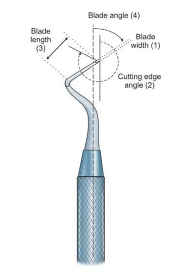
Fig. 5.5: Instrument formula
The first number of the formula indicates width of the blade or primary cutting edge in tenths of a millimeter (Fig. 5.6).
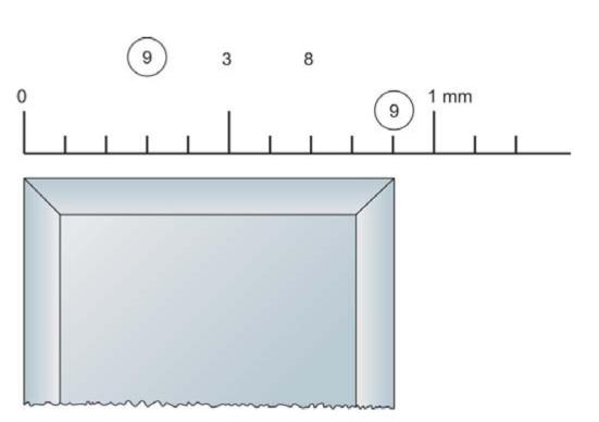
Fig. 5.6: First digit of formula indicates width of blade in 1/10th of a millimeter
The second number represents the angle formed by the primary cutting edge and long axis of the instrument handle in clockwise centigrade. The instrument is positioned in such a way that the number always exceeds 50 and is measured in clockwise centigrades. If the cutting edge is at right angle to the length of the blade, then this number is omitted.
The third number (second number in three number code) represents the length of the blade in millimeters, that is, from the shank to the cutting edge (Fig. 5.7).
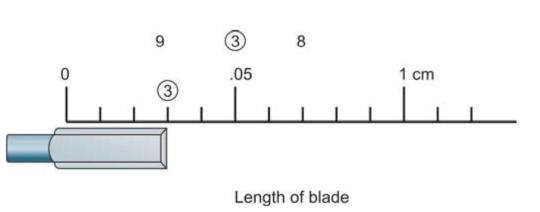
Fig. 5.7: Third number indicates length of blade in millimeters
The fourth number (third number in three number code) represents the angle which the blade forms with the long axis of the handle or the plane of the instrument in clockwise centigrade. To calculate the measurement of the angle, place the instrument on the center of the circle and move it until the blade lines up with one line on the ruler. This measurement represents the angulation of the blade from the long axis of the handle. To keep balance during working, tip of blade is brought in the line of the long axis of the handle.
Example:
1. An instrument having instrument formula of 15-8-14 indicates following:
• 15 represents the width of the blade in tenths of a millimeter, i.e. 1.5 mm.
• 8 represents the length of the blade in millimeters, i.e. 8 mm.
• 14 represents the blade angle in centigrades.
2. Instrument with formula 15-95-8-12 represents the following:
• 15 represents width of the blade in tenths of a millimeter, i.e. 1.5 mm.
• 95 represents the cutting edge angle in centigrades.
0 8 represents length of the blade, i.e. 8 mm.
0 12 represents blade angle in centigrades.
Bevels in Cutting Instruments
Single Bevel Instruments
Most of the instruments have single bevel that forms the primary cutting edge. These are called single beveled instruments. These can be right or left bevel and mesial or distal bevel instruments (Figs 5.8A and B).
Figs 5.8A and B: Different bevels of an instrument (A) Straight chisel with single bevel, (B) Bibeveled instrument
Right and left bevel instruments: Single-beveled direct cutting instruments such as enamel hatchets are made in pairs having bevels on opposite sides of the blade. These are named as right and left bevel instruments. During use, move the instrument from right to left in right beveled instrument and from left to right in left bevel instrument.
Identification of bevel. Hold the instrument in such a way that the primary cutting edge faces downwards and pointing away from operator. If bevel is on the right side of the blade, the instrument is right sided and if bevel is on the left side of the blade the instrument is left sided.
Mesial and distal bevel instrument: If we observe the inside of the blade curvature and the primary bevel is not visible then the instrument has a distal bevel and if the primary bevel can be seen from the similar viewpoint the instrument has a mesial or reverse bevel.
Bibeveled Instrument
If two additional cutting edges extend from the primary cutting edges, then the instrument with secondary cutting edges is called bibeveled instrument.
Triple-beveled Instrument
If three additional cutting edges extend from the primary cutting edge, then the instrument is called triple-beveled instrument.
Instrument Motions
Pulling. Here, instrument is moved towards operator’s hand.
Scraping. Here, instrument is move side-to-side or back and forth on the tooth surface.
Pushing. Here, instruments is moved away from operator’s hand.
Cutting. Here, instrument is used parallel to the long axis of handle.
EXPLORING INSTRUMENTS
Mouth Mirrors
Mouth mirrors are used as supplement to improve access to instrumentation (Figs 5.9A to D).
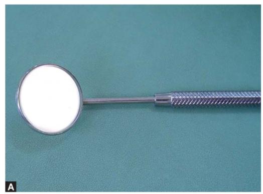
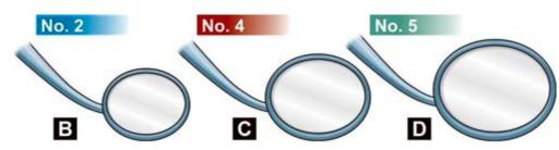
Figs 5.9A to D: (A) Photograph showing mouth mirror (B to D) Different sizes of mouth mirrors
Types of Mirror Faces
1. a. Front surface reflecting mirror
b. Rear surface reflecting mirror
2. a. Plane or flat surface
b. Concave surface: Reflecting surface on the front of lens and produce a clear image. It is mirror of choice
3. a. One sided-image on one side
b. Two sided-image on either side (Advantageretraction with indirect vision simultaneously).
Uses of Mouth Mirror
• Direct vision: Retraction is done with mirror to enhance visibility in specific area. Illumination allows the dentist to use mirror a spotlight to reflect light from dental light on to a specific area of oral cavity. For example, use in maxillary left palatal aspect.
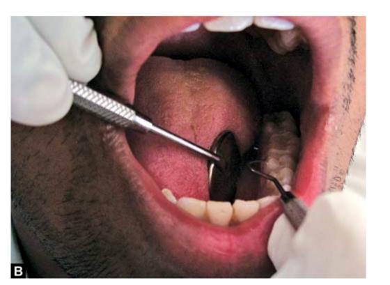
• Indirect illumination: In this, mirror is placed in oral cavity that cannot be seen directly without compromising dentist’s position. For example, use in maxillary right palatal area and for palatal surfaces of anterior teeth (Fig. 5.10).
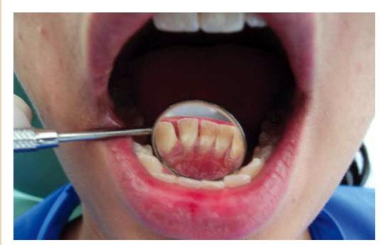
Fig. 5.10: Mirror used for indirect vision of lingual surfaces of mandibular anterior teeth
• Transillumination: Mirror is placed behind the teeth and direction of light perpendicular to long axis of teeth.
• Retraction: Retraction of soft tissue such as tongue and cheeks to aid in better visualization of the operating field (Figs 5.11A and B).
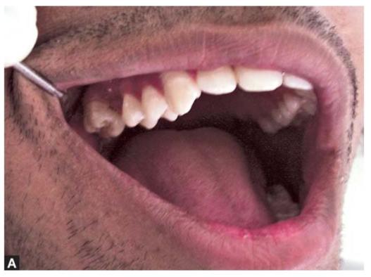
Figs 5.11A and B: (A) Mirror helps in retraction of cheek, (B) Tongue can be retracted using mirror
Uses of mouth mirror
• Direct vision
• Indirect illumination
• Retraction
• Transillumination
Explorer
Explorer is commonly used as a diagnostic aid in evaluating condition of teeth especially pits and fissures (Figs 5.12A to D).
Parts
• Handle of explorer is straight which could be plain or serrated.
• Shank of explorer is curved with one/more angle.
• Working tip of explorer is pointed.
Types of Explorer
• Straight explorer: It is bent perpendicular to the handle. This is used for examining occlusal surfaces of teeth.
• Shepherd’s Crook or curved explorer: It has semilunarshaped working tip perpendicular to the handle. This is used for examining occlusal surfaces.
• Interproximal explorer/Briault explorer/Back action probe: Commonly used for examination of interproximal surfaces of teeth, this explorer has two more angles in the shank with working tip-pointed towards the handle.
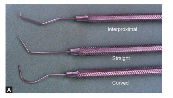
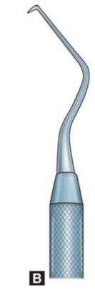
Figs 5.12A to D: Different types of explorers
Tweezers
These have angled tip and are available in different sizes (Figs 5.13A and B). They are used to place and remove cotton rolls and other small materials.
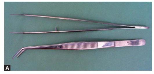
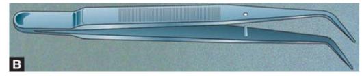
Figs 5.13A and B: (A) Tweezers, (B) Diagrammatic representation of tweezer
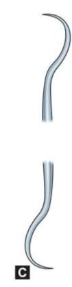
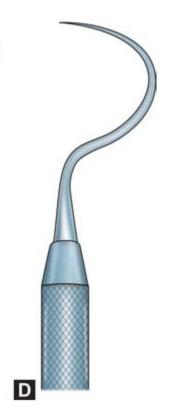
Periodontal Probes
Though they almost look like explorers but they have blunt end which is marked with graduations (Fig. 5.14). They are used for measuring pocket depth and tooth preparations.
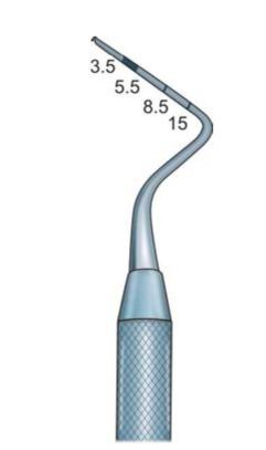
Fig. 5.14: Periodontal probe
HAND CUTTING INSTRUMENTS
Instrument Families
Many dental procedures require the use of hand instruments with sharp cutting edges. They are used in the tooth preparation procedures for amalgam, composite and other restorations. All instruments can be basically divided in into two families:
• The chisel family consisting of chisel, hoe, angle former and cleoid-discoid.
• The hatchet family consisting of hatchet, gingival margin trimmer and spoon excavator.
Chisels
Chisels are used for cleaving, planing and lateral scraping. In other words, they are used to split tooth enamel, to smooth preparation walls and to sharpen the preparations. Chisels are used with a push motion.
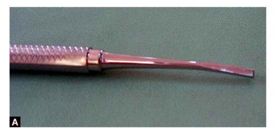
Straight Chisel
In straight chisel, the cutting edge of the chisel makes a 90° angle to the plane of the instrument. It is used for gingival restoration of the anterior teeth (Fig. 5.15).
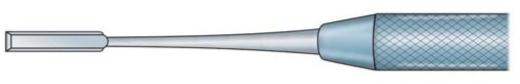
Fig. 5.15: Chisel
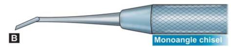
Angled Chisel
In angled chisels, the primary cutting edge is in a plane perpendicular to the long axis of the shaft and may have either a mesial or distal bevel. They are used with a push or pull motion for anterior proximal restorations, smoothening proximal walls and gingival walls for full coverage restorations (Figs 5.16A and B).
Figs 5.16A and B: Angled chisels; (A) Biangled, (B) Monoangle chisel
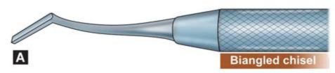
The two most common types used in operative dentistry are the Wedelstaedt and biangle chisels (Fig. 5.17). The Wedelstaedts have slightly curved shanks. They are mainly used on anterior teeth. The biangle chisels have two different angles-one at the working end and other at the shank. This design permits access to tooth structures which are not be possible with straight chisels.
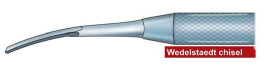
Fig. 5.17: Wedelstaedt chisel
Hoes: Dental hoes resemble a miniature garden hoe. By definition, the hoe is any instrument where the blade makes more than a 12.5° angle with the plane of the instrument (Fig. 5.18). Commonly hoe blades make 45 to 90° angle to the long axis of handle. Its shank can have one or more angles (Figs 5.19A and B). Hoe is used with a pulling motion. Hoe is used to smooth and shape the floor and form line angles in class III and V restorations.
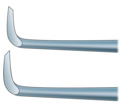
Fig. 5.18: Hoe
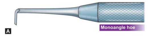
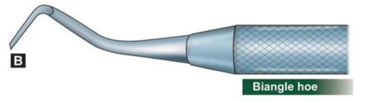
Figs 5.19A and B: Monoangle and biangle hoe
Chisel vs Hoe
By definition chisel is an instrument where the blade makes up to 12.5° angle with the plane of the instrument, whereas in hoe, the blade is angled more than a 12.5° with the plane of the instrument.
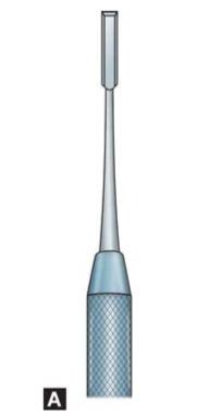
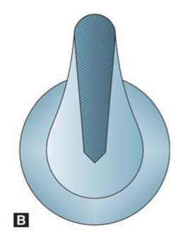
Angle Former
Angle former is a type of excavator which is monoangled with the cutting edge sharpened at an angle to the long axis of the blade. Angle of cutting edge to blade axis lies between 80 to 85 centigrades (Figs 5.20A and B). Blade of angle former is beveled on sides as well as the end, this forms three cutting edges. It is used with a push or pull motion for accentuating line and point angles, to establish retention form in direct filling gold restoration.
There are two sets of angle formers, mesial and the distal angle former. Each instrument in the set is a doubleended instrument.
The mesial angle former is used to plane the gingival cavosurface margin in the mesial proximal box. The distal angle former is used to plane the gingival cavosurface margin in the distal proximal box.
Cleiod-discoid
It is modified chisel with different shape of cutting edges (Figs 5.21A and B). In cleoid, it is claw-like and in discoid it is disk-like, instead of a sharp edge, the edge is rounded. These instruments have sharp cutting edges as spoon excavators but blade to shaft relationship is similar to chisels. They are used for removing caries and carving amalgam or wax patterns.
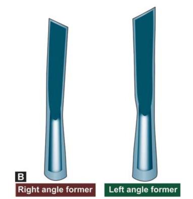
Figs 5.20A and B: Angle formers
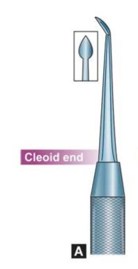
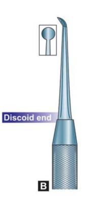
Figs 5.21A and B: Cleoid-discoid
Hatchet
Any instrument where the cutting edge is parallel or close to parallel to the plane of the instrument is called a hatchet. Basically, a hatchet is the similar to as an axe except that it is much smaller (Figs 5.22A and B).
Figs 5.22A and B: Hatchet
Hatchet is a paired instrument in which blades make 45 to 90° angle to the shank. In paired right and left hatchets blades are beveled on opposite sides to form their cutting edges (Figs 5.23A and B).
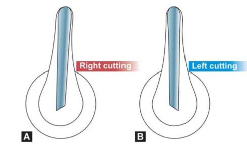
Figs 5.23A and B: Right and left cutting hatchets
Some hatchets have single cutting ends and some have cutting edges on both ends of the handle. Hatchets are used for cleaving enamel and planning the dentinal walls so as to have sharp outline of the preparation.
Some hatchets are bibeveled, i.e. blade has two bevels with cutting edge in the center. These bibeveled biangle hatchets are used in a chopping motion to refine line and point angles.
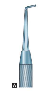
Spoon Excavator
The spoon excavator is a modified hatchet. It is a doubleended instrument with a spoon, claw, or disk-shaped blade (Figs 5.24A and B). Spoon excavator is used to remove caries and debris in the scooping motion from the carious teeth.
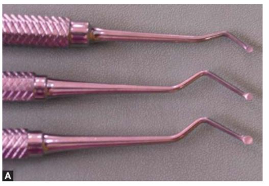
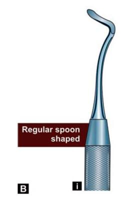
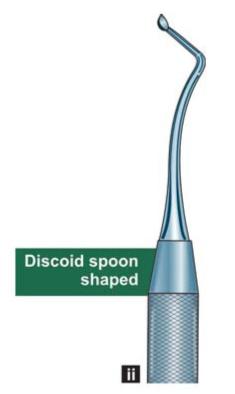
Figs 5.24A and B: Spoon excavators; (i) Regular spoon shaped, (ii) Discoid spoon shaped
Two main differences between the spoon excavator and hatchet
1. The blade of a spoon excavator is curved to emphasize the lateral scraping motion.
2. The cutting edge of the spoon excavator is rounded.
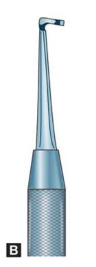
Gingival Margin Trimmer (GMT)
The gingival margin trimmer (GMT) is a modified hatchet which has working ends with opposite curvatures and bevels (Figs 5.25A and B).
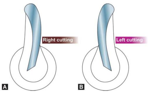
Figs 5.25A and B: (A) Right cutting, (B) Left cutting end of a paired GMT
Stay updated, free dental videos. Join our Telegram channel
VIDEdental - Online dental courses


