Fig. 5.1
Surgical curettes used to reflect the Schneiderian membrane from the maxillary sinus floor
Piezoelectric device and corresponding tips (Please see details in the section: Piezoelectric surgery in SFE)
5.3.4 Technique Description
5.3.4.1 Flap Design
The flap design depends on several factors including:
-
Full or partially edentulous ridge
-
Neighboring crown restorations
-
Amount of keratinized gingiva
-
Shape and volume of the maxillary sinus
-
Simultaneous or delayed implant placement
-
The need to combine a lateral and/or vertical bone augmentation
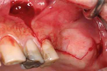 Fig. 5.2Typical midcrestal, mesial, and distal releasing incisions: note the wider base of the flap to respect the blood supply
The incision line is designed to avoid the planned location of the lateral window. Most commonly, the initial incision is midcrestal extending well beyond the planned extension of the osteotomy (Fig. 5.2).
Sometimes, this incision is made slightly palatal to the crest (2–4 mm) to preserve a wider band of keratinized attached gingiva for a more solid wound closure and to avoid wound dehiscence. However, an incision made too far palatally may result in soft tissue dehiscence due to compromised blood supply (Kleinheinz et al. 2005).
When a staged approach is indicated, it would be recommended to place the incision line slightly on the buccal aspect (within the keratinized gingiva) of the crest as this may offer easier and quicker access for window opening. Moreover, the incision line should not cross the planned area of the lateral window. Wound edges lacking bone support may give rise to soft tissue collapse or major dehiscences in the absence of blood supply.
-
The incision is carried on forward beyond the anterior border of the maxillary sinus. In case of the presence of neighboring teeth, the incision starts from the mesial area of the anterior tooth and extends intrasulcular until the distal portion of the posterior tooth.
-
Releasing incisions are made anteriorly extending into the buccal vestibulum to facilitate reflection of a full-thickness mucoperiosteal flap; very often, the releasing incision is made immediately posterior to the canine tooth, which in most dentated cases was the posterior remaining tooth to avoid the infraorbitary plexus (Fig. 5.3).
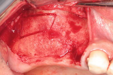 Fig. 5.3Slightly buccally displaced midcrestal incision; releasing incision immediately posterior to the canine avoiding the infraorbitary plexus
However, we try to avoid vertical incisions whenever possible, as they tend to increase the discomfort in the postoperative phase.
5.3.4.2 Mucoperiosteal Elevation (Fig. 5.4)
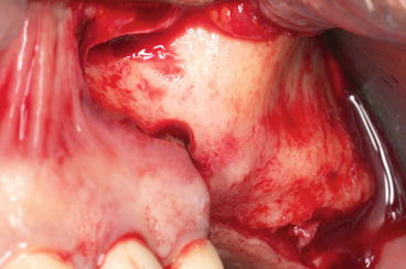
Fig. 5.4
Flap reflection (difficult) in case of a prominent zygoma buttress
A mucoperiosteal full-thickness flap is raised slightly superior to the anticipated height of the lateral window (antral wall). The flap reflection should reach the zygoma buttress in order to clearly visualize the lateral side of the maxilla. The reflection should be extended beyond the borders of the future osteotomy (window).
Once the flap has been raised to a desired level, the osteotomy step could start.
PS: In case of recently extracted teeth, showing a localized perforation of the bone, the flap reflection should be done through a careful split flap dissection in order to avoid a tearing of the Schneiderian membrane.
5.3.4.3 Sinus Window Osteotomy
Different surgical techniques to access the sinus cavity were described by clinicians.
The window size and position of the lateral maxillary wall are designed according to the planned location(s) of the implant(s) and anatomic conditions.
The sinus cavity is identified due to the lack of blood supply compared to the surrounding cortical, and is often bluish in case of a thin cortical bony wall (Fig. 5.5).
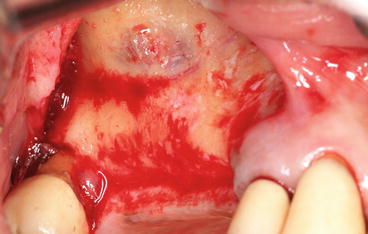
Fig. 5.5
Thin cortical bony wall showing bluish sinus membrane
The bony window is either completely removed while the sinus membrane is carefully elevated to create a space for the grafting material or mobilized together with the attached bone window and rotated medially while preserving the sinus membrane intact.
The original modified Caldwell-Luc technique (top-hinge-trapdoor technique) (Tatum 1977), commonly referred to as the lateral window or lateral approach, describes a method of opening a bony window inward using a top hinge in the lateral maxillary sinus wall; the osteotomy is prepared in a superior position just anterior to the zygomatic buttress.
Two other positions have also been described: a mid-maxillary position between the alveolar crest and zygomatic buttress area, and a low anterior position near the level of the existing alveolar ridge (Lazzara 1996; Zitzmann and Schärer 1998).
Important
-
The crestal part of the window (osteotomy) should be higher than the sinus floor in order to contain the bone substitute.
-
The shape of the window is generally pyramidal (the top of the pyramid is crestal), with rounded angles in order to avoid membrane tearing.This shape could be modified depending on several factors including:
-
The presence of septa: a W shape is suggested in case of a short septum; if not, two windows surrounding the septum should be performed.
-
The position of the PSAA (posterior superior alveolar artery) (detected on the CBCT) should be also considered to draw the osteotomy margins in order to avoid uncontrolled bleeding.
The osteotomy borders will then be shifted and leveled accordingly.
Lateral SFE approach today involve numerous antrostomy designs: below, a description of three different methods for handling the buccal cortical bone plate in order to introduce the selected bone substitutes.
Top-Hinge Trapdoor Technique (Figs. 5.6 and 5.7)
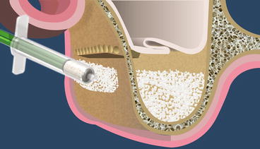
Fig. 5.6
Schematic drawing of the top-hinge-trapdoor SFE
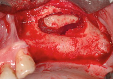
Fig. 5.7
Clinical view showing the reflected membrane and the trapdoor hinged toward the future sinus floor
The originally described technique was the “trapdoor technique” similar to the Caldwell-Luc approach or in fracturing of the cortical bony plate like a trapdoor and using it as the superior border of the sinus compartment leaving it attached to the underlying Schneiderian membrane.
-
After the lateral sinus wall has been exposed, round carbide burs (or piezoelectric surgery tips) are used to mark the outline of the osteotomy.
-
A rectangular osteotomy is trimmed with round carbide burs (# 6 and 8) to create a U-shaped trapdoor into the lateral antral wall (lateral buttress of the maxilla).
-
Osteotomy procedure must be done with a light touch and a brushing stroke so not to tear the Schneiderian membrane.
-
The osteotomy runs from the area of the first or second molar posteriorly to the anterior extent of the maxillary sinus.
The first to be done is the inferior horizontal segment of the rectangle, which is made as close as possible to the floor of the sinus and no more than 2–3 mm above the floor.
This helps keeping the graft material in place in the floor of the sinus.
The superior horizontal segment of the rectangle is performed by drilling closely positioned holes.
This creates a trapdoor, which will be fractured inward and displaced medially while hinging on its superior margin (along the superior aspect of the rectangle).
-
The height of this trapdoor should not exceed the width of the sinus (it can be measured in computerized tomography) to allow for a final horizontal position of the new floor.
The infracturing is done carefully to prevent tearing of the Schneiderian membrane during its elevation from the floor of the antrum.
It is important to free up the sinus membrane in all directions (anteriorly, posteriorly, and medially) before attempting to intrude the trapdoor medially.
Once the window is created and the membrane exposed, the bone that is adherent is rotated in medially.
It then becomes the new floor of the maxillary sinus.
Since the cortical bony plate is resistant to bone resorption, this may protect the graft.
The space created after the sinus membrane has been elevated by the intruded trapdoor is now ready to receive the bone grafting material in the next stage.
Repositioned Bony Window Trapdoor (Video 5.1) (Figs. 5.8, 5.9, 5.10, and 5.11)
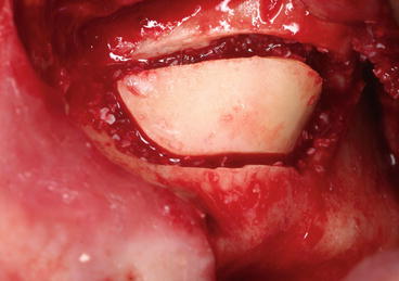
Fig. 5.8
Thick bony plate repositioned over the grafting material
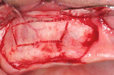
Fig. 5.9
Piezoelectric bony window preparation: note the PSAA artery showing by transparency via the thin buccal plate
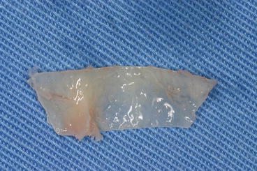
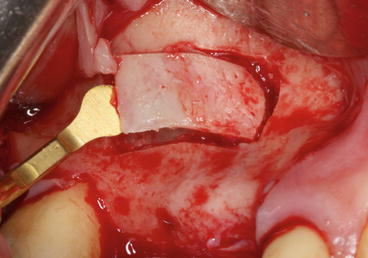
Fig. 5.10
Thin bony plate removed, before its repositioning following the grafting procedure
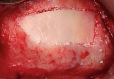
Fig. 5.11
Thin bony plate repositioned in place containing the particulate bone substitutes
Other methods propose the removal and preservation of the buccal plate.
In this situation, following the preparation of a rectangular osteotomy using a mechanical (burs or microsaw) or piezoelectric tips, lateral window is gently mobilized, a small periosteal elevator or a Freer elevator is carefully inserted into the osteotomy line, and via an elevating motion that set the fulcrum on the intact maxillary wall, the bony window is easily detached from the underlying sinus membrane and stored in saline.
The sinus membrane is dissected around the margins of the window and extended inferiorly to expose the floor of the sinus in the edentulous area.
The bony plate will then be repositioned in place on the lateral aspect of the graft material without rigid fixation.
Lundgren et al. (2008) demonstrated the key role of replaceable bone window technique (using an oscillating saw with a thin blade) in a successful SFE procedure.
Bone cutting should be ideally performed in an oblique direction (thick buccal plate), resulting in a flanged bone window capable of being replaced in a stable position.
The rationale for this method was the notion that the lateral window would not completely heal without replacement of its cortical plate that could also stabilize the grafting material (Kim et al. 2014).
Some advantages of using a repositioned bony window:
-
Soft tissue from the overlaying oral mucosa does not penetrate to the sinus cavity.
-
The fact that air cannot pass through the bony window reduces the risk of disturbing the sinus membrane and the underlying blood clot; the bone window replacement technique may help to reestablish proper pneumatic conditions (Timmenga et al. 1997).
-
It is possible that the surface of the bony window contributes to a prolonged period of healing, passively by serving as a stabilizing surface for the blood clot and actively by promoting bone formation beneath the elevated sinus membrane.
-
Replaceable bony window acts as an osteoinductive autologous barrier membrane over various bone graft materials and accelerates new bone formation (Kim et al. 2014).
However, healing of the lateral window by bone apposition has been demonstrated to occur without replacing the cortical bony plate (Boyne 1993).
This bony plate could be also positioned in another sites for lateral ridge augmentation (2D or 3D) (Fig. 5.12).
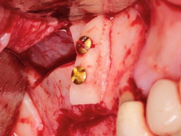
Fig. 5.12
Thick bony plate reclined and positioned anteriorly for an onlay 2D ridge augmentation in the premolar region
The main indication for this technique is the presence of a thick lateral sinus wall since:
-
In case of a complete osteotomy procedure, a thick bony wall may be a time-consuming problematic barrier requiring additional efforts to reach the Schneiderian membrane.
-
In case of a classical “trapdoor hinge technique,” a thick lateral maxillary wall that often resists inward movement is better removed and repositioned later.
The third surgical technique and the most commonly reported is the preparation of an access hole by removing the entire buccal bone plate (thinning of the buccal bone to a paper-thin bone lamella prior to the elevation of the sinus membrane).
-
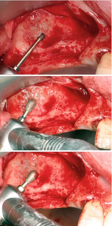
In case of a thick bony window, it is less time-consuming to first reduce the thickness of the wall: the bone is trimmed down to a thin bony plate with a round carbide bur, a piezoelectric tip, or a bone scraper (Figs. 5.16, 5.17, and 5.18).
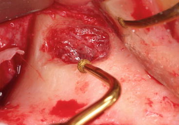 Fig. 5.16Complete osteotomy using a piezoelectric round tip, minimizing the risk of membrane perforation
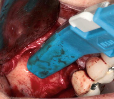 Fig. 5.17Bone scraper trimming the buccal plate in order to reduce the thickness of the wall
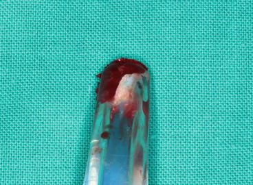 Fig. 5.18Particulate autogenous bone collected using a bone scraper ready to be mixed with bone substitutes
 -
Upon confirmation that the sinus membrane is visible through the window, the round carbide bur is switched with a round bur or a diamond-coated smoothing piezoelectric insert (see Fig. 5.16) to refine the window and minimize the risk of unintended perforation of the sinus membrane. The bone removed by osteoplasty could be harvested and incorporated within the sinus graft.
-
The preparation is continued until a bluish hue of the sinus membrane is observed.
-
The osteotomy border should be as smooth as possible, avoiding cutting edge in order to reduce the risk of membrane tearing.
Window preparation is a critical step. Perforations of the membrane occur frequently during this step and are the main reason of aborting the SFE procedure. The use of piezoelectric devices is recommended to increase safety and reduce complications related to Schneiderian membrane tearing.
5.3.4.4 Lifting the Schneiderian Membrane (Figs. 5.19, 5.20, and 5.21)
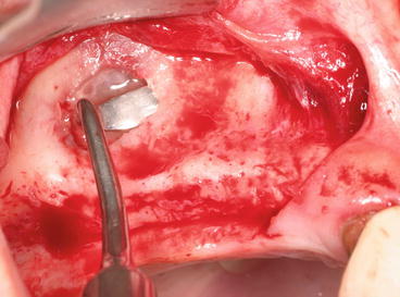
Fig. 5.19
Short and smooth sinus curette initiating the membrane lifting
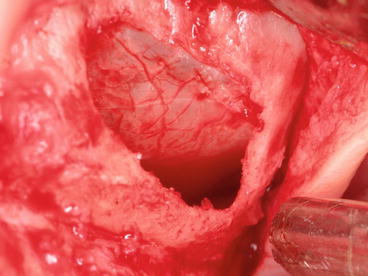
Fig. 5.20
Schneiderian membrane lifted in all directions: anteriorly, posteriorly, and medially
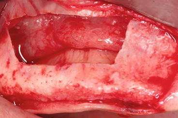
Fig. 5.21
Membrane elevation should reach the medial wall in order to optimize a tension-free grafting material introduction for a 3D regeneration (filling)
Care must be taken to perform a 3D membrane elevation: it is important to free up the sinus membrane in all directions (mesially, distally, and medially).
The membrane at the inferior aspect of the osteotomy is dissected from the floor of the maxillary sinus and elevated upward to create a space in the floor of the sinus for the bone-graft material. This procedure will be performed according to the technique used.
If the buccal wall is eliminated (complete antrostomy), the sinus membrane is elevated directly with blunt instruments, broad-based freers, and curettes with different angulations to access the different walls of the sinus. It is recommended to use smooth and large end curettes in order to reduce the trauma. Dedicated piezoelectric inserts are also available. They are particularly useful to start the lifting procedure especially in the presence of a septum (Figs. 5.22 and 5.23).
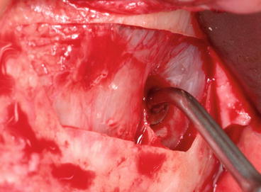
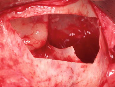
Fig. 5.22
“Bell-shaped” tip facilitating the lifting procedure toward the knife-edge septum
Fig. 5.23
The presence of a septum with a sharp edge jeopardizing the integrity of the Schneiderian membrane
Usually, membrane elevation starts at the edges, using a short curette, increasing gradually the amount of membrane elevation from the superior border of the osteotomy, proceeding approximately 2–3 mm mesially, toward the mesio-superior line angle and along the mesial part of the window, and effecting detachment of a portion of the sinus membrane from the alveolar bone.
We proceed to the next step only once we have released the membrane at least 2 mm along the superior, mesial, and distal borders of the bony window, allowing the passive insertion of longer curettes into the created space. Surgical curettes should be permanently in tight contact with the underlying bony walls in order to minimize membrane tearing.
Care should be taken to perform 3-dimensional membrane lifting in order to decrease incidence of sinus membrane perforation.
Excessive pressure in a specific area while reflecting the membrane may lead to a perforation.
Moreover, the membrane must be elevated higher than the superior osteotomy to prevent excessive pressure on the bone-graft material.
It is also important to reflect the membrane up to the medial (palatal) wall (see Fig. 5.21) of the maxillary sinus in order to avoid membrane overlapping, thus resulting in incomplete bone regeneration at the palatal wall of the implant.
The limits of the reflected area are strongly related to the desired area to be grafted and the positions of the future implants (delayed or simultaneous).
-
In case of “complete osteotomy” or “repositioned bony window”) procedures, the reflected membrane becomes the superior (and distal) wall of the compartment that will receive the osseous graft.
-
In the trapdoor hinge technique, gentle tapping is continued until complete movement of the bony plate is observed. The bone trap that was fractured inward in combination with the elevation of the sinus membrane and rotated upward will create the roof and provide adequate space for grafting material. Care should be taken not to perforate the sinus membrane at this step.
Septa Incidence on SFE (Figs. 5.24 and 5.25)
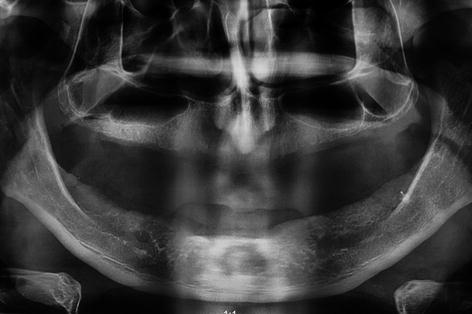
Fig. 5.24
Panoramic radiograph showing a vertical septum protruded in the sinus cavity
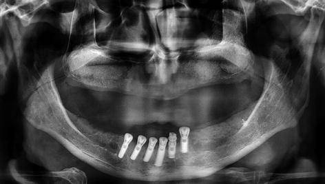
Fig. 5.25
One-month postoperative radiography after sinus grafting
These septa were first described by the anatomist Underwood13 in 1910 and are thus also referred to as Underwood’s septa.
The presence of septa in the region of the sinus floor (bucco-palatal or mesio-distal) can cause complications during SFE procedures; while they can limit creation of a window in the lateral antral wall and elevation of a hinge door, there is a risk of tearing the Schneiderian membrane of the maxillary sinus when elevating it from an alveolar recess containing several septa.
If septa are encountered in the antral floor during SFE procedures, Boyne and James (1980) recommended cutting them with a narrow chisel (or a piezoelectric device nowadays) and removing them with a hemostat so that the bone graft can be placed completely across the antral floor without interruption. If septa are left in situ during SFE, the Schneiderian membrane is at risk of being torn, particularly at the cranial edge of the septum, when being elevated. Moreover, septa can impede the view of the sinus floor and may limit placement of grafting material, thus preventing adequate filling of the sinus floor.
An interesting alternative would be to perform two different osteotomies from each side of the septum, as if we are in the presence of two side-by-side sinuses (Fig. 5.26).
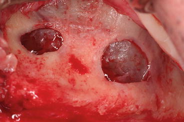
Fig. 5.26
Two distinct entries to reach the sinus from each side of the septum
While rotary instruments are commonly used for window preparation, surgical curettes for membrane elevation, the recent development of piezoelectric ultrasonic devices may contribute to reduce intraoperative complications such as membrane perforation (Wallace et al. 2007).
5.3.4.5 Introduction of the Grafting Material into the Sinus (Fig. 5.27)
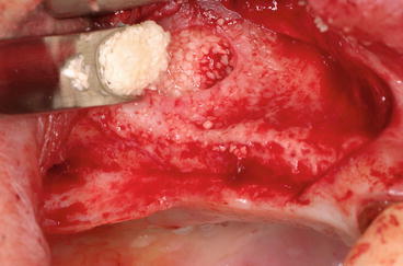
Fig. 5.27
Packing the grafting material in the created space under the membrane
The resulting space created after membrane-lifting inward is packed with bone-graft material that is placed under the membrane. The grafting material should be pushed through the window in all directions: mesially and distally with the help of instruments such as pluggers, periosteal elevators, or even osteotomes. Most importantly, it must reach the medial wall of the maxillary sinus. It should be placed in the cavity loosely, avoiding overpacking.
The surgeon should add an additional 20 % of bone-grafting material to counteract the loss of originally grafted volume. After the grafting material is placed into the sinus, the mucoperiosteal flap is repositioned combined or not to membrane placement over the lateral window (Figs. 5.28 and 5.29).
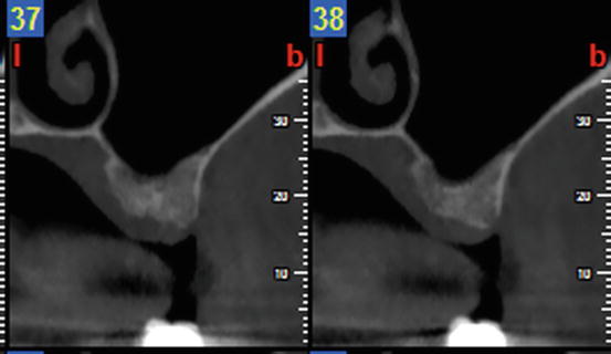
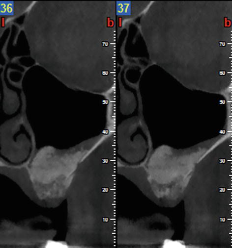
Fig. 5.28
Preoperative CBCT prior to lateral SFE
Fig. 5.29
Postoperative CBCT at 8 weeks showing the graft remodeling
5.3.4.6 Membrane Placement (Fig. 5.30)
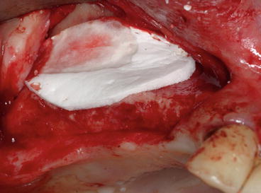
Fig. 5.30
Absorbable collagen membrane protecting the grafting material
Conflicting results concerning the benefits of placing a membrane over the lateral window have been reported.
Many investigators claimed positive results with barrier membrane placement over the lateral wall in SFE (Wallace et al. 2005; Small et al. 1993; Hürzeler et al. 1996; Peleg et al. 1999; Lorenzoni et al. 2000) and revealed a tendency for better bone formation and less implant failures (Tawil and Mawla 2001; Pjetursson et al. 2008). On the opposite, a recent review (Klijn et al. 2012) with histomorphometric data following SFE with autografts alone did not confirm any effect of a barrier membrane on bone formation.
The membrane barrier is used to cover the osteotomy site extending 2–3 mm beyond its borders, promoting hemostasis, and preventing graft disruption at the time of suturing (Avila et al. 2010).
Depending on the authors, the membrane is stabilized (with tacks or screw) or not. As in a GBR procedure, the membrane appears to exclude non-osteogenic soft tissue invasion from the grafted sinus, with a resultant increase in vital bone formation and an increased rate of implant survival.
Fewer studies have compared the results achieved with and without barrier membranes (Froum et al. 1998; Tarnow et al. 2000; Tawil and Mawla 2001).
Note
-
It appears that covering the lateral window with a membrane may have a beneficial effect. Previous studies reported that:1.Vital bone formation in SFE is improved when a membrane is placed over the window.2.Vital bone formation is similar with nonabsorbable and absorbable membranes.3.Implant survival rate is similar with nonabsorbable and absorbable membranes.
Overall, it is recommended to use a membrane over the lateral window in clinical situations characterized by a limited osteogenic potential of the patient or the bone substitute used.
5.3.4.7 Suturing Technique (Fig. 5.31)
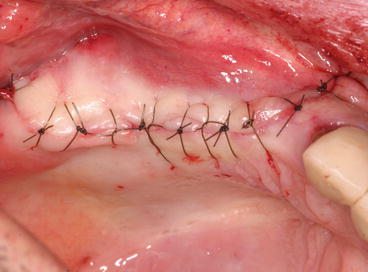
Fig. 5.31
Proper flap closure using uninterrupted sutures on the top of the crest and single sutures for the releasing incisions
Suturing technique should insure proper flap closure without tension in order to maintain hemostasis and to prevent bone exposure through healing by primary intention.
Single interrupted sutures (5/0 or 4/0) are mainly used for the releasing incisions.
Uninterrupted sutures are used specifically on the top of the ridge in case of delayed or submerged implant placement; the stitch is commenced at one extremity of the wound (generally at the posterior extremity) and after the needle is passed through the two lips. It is then carried under the slack of the thread, so that the loop of each stitch after being tightened shall be at right angles to the edge of the wound, while the portion intervening between the stitches is parallel to it. This kind of suturing technique provides adequate tension for wound closure, but loose enough to prevent tissue ischemia and necrosis.
Sutures should be removed 10 days to 2 weeks following the SFE procedure.
5.3.5 Contribution of Piezoelectric Surgery in SFE
Piezoelectric surgery is a hard tissue surgical application using multipurpose high-end ultrasonic device that was originally developed for the atraumatic cutting of bone by way of ultrasonic vibrations and as an alternative to the mechanical instruments that are used in conventional oral surgery.
A critical feature of a piezosurgery unit is the ability to vary the oscillation frequency and the cutting energy resulting in the selective cutting of bone without damaging the adjacent soft tissue (e.g., vessels, nerves or specifically sinus membrane in SFE), providing a clear visibility in the operating field due to pressurized irrigation and cavitation effect, and cutting with micron sensitivity without the generation of heat. Specific inserts are some three times more powerful than conventional ultrasonic units, which allow them to cut highly mineralized cortical bone. The reduced range and the linearity of the vibrations allow for precise control of cutting. The cutting characteristics of piezosurgery are mainly depending upon the degree of bone mineralization, the design of the insert, the applied pressure on the handpiece and the speed of movement during usage.
All of the surgical techniques to elevate the maxillary sinus present the possibility of perforating the Schneiderian membrane. This complication can occur during the osteotomy, which is performed with burs, or during the elevation of the membrane when using surgical manual curettes. The piezoelectric osteotomy of the bony window easily cuts mineralized tissue without damaging the soft tissue; moreover, sinus membrane elevation from the sinus floor is performed using both piezoelectric elevators and the force of a physiologic solution subjected to piezoelectric cavitation without causing perforations.
Over the past two decades, an increasing amount of literature has shown that piezoelectric devices are innovative tools in oral surgery (Fig. 5.32). Numerous publications have also shown the benefits of their use in SFE (Vercellotti et al. 2001, 2005; Wallace et al. 2007).
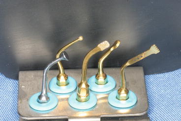
Fig. 5.32
Piezoelectric kit including various tips used in the different steps of SFE
Piezosurgery can be particularly useful for the preparation of the bony window (diamond-coated square or bell-shaped tips) (see Fig. 5.16) and in atraumatic dissection of the thin and delicate sinus membrane with specially designed tips (rounded, dull, bell-shaped, or curette-shaped tips) (Fig. 5.33).
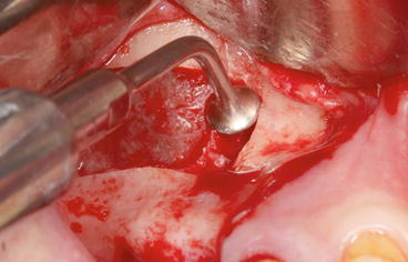
Fig. 5.33
“Bell-shaped” piezoelectric tip initiating the dissection of the Schneiderian membrane
Piezoelectric SFE surgery has been described by Vercellotti et al. (2001) (Vercellotti et al. 2005) who demonstrated its clinical effectiveness and a better tissue response based on histologic and histomorphometric evidence of wound healing and bone formation; the tissue response is more favorable to piezosurgery than to diamond or carbide rotary instrumentation (Vercellotti et al. 2005).
When the lateral wall is thin, it is advised to use the diamond ball smoothing insert or the diamond scalpel to outline the window.
If the wall is thick, it is less time-consuming to first reduce the thickness of the wall with the osteoplasty insert and then refine the window with the diamond-coated smoothing insert.
The bone removed by osteoplasty can be harvested and incorporated within the sinus graft.
The initial release of the membrane from the antrostomy edges is performed with a dull, rounded, noncutting elevator that works with saline cavitation to safely create a small internal elevation (Vercellotti et al. 2001). The procedure is often completed with conventional sinus membrane curettes.
While perforation of the sinus membrane is the most common complication (14–56 %) in SFE when using rotary instruments (Testori et al. 2008), Wallace et al. (2007) reported that piezosurgery could significantly minimize sinus perforation rates (3–7 %). Consequently, piezosurgery offers a 75 % reduction in the expected perforation rate.
Further, the occurrence of perforations appears to be equally attributable to rotary instrumentation, initial release of the membrane at the antrostomy margin with hand instruments, and the continued elevation of the membrane from the internal sinus walls.
Various tips are specifically designed for SFE. Light handpiece pressure and an integrated saline coolant spray keep the temperature low and the visibility of the surgical site high. It is claimed that inadvertent perforations of the sinus membrane are unlikely when piezosurgical techniques are appropriately applied.
Stay updated, free dental videos. Join our Telegram channel
VIDEdental - Online dental courses


