Fig. 10.1
Histological section of an osseointegrated implant. The red part is the bone; the black item is the implant. Notice the tight adaptation of bone to the implant. Thirty-five percent to 40 % of the mineralized content is in contact with the implant surface
Even given these limitations, IOR still provides some degree of quantitative and qualitative analysis that may be extremely useful. The purpose of this chapter is to evaluate and give guidance to the clinician regarding the appropriate use of IOR, specifically during the restorative phases of implant therapy and subsequent monitoring and follow-up.
IOR, Bone-to-Implant Contact and Health of the Tissues
Implant dentistry frequently focuses on the bone directly adjacent to the implant. In fact, osseointegration is defined as “the apparent direct attachment or connection of osseous tissue to an inert, alloplastic material without intervening connective tissue.” Although radiographic assessments of bone adjacent to the dental implant are made, it should be understood that direct implant–bone contact cannot be accurately determined. Because IOR is two-dimensional, there exists an inability to discern bone levels directly facial and lingual to the implant body, as these sites will be obscured by the implant itself. Even at interproximal sites adjacent to the implant, bone attachment cannot be easily determined.
A study on the accuracy of radiographs to diagnose radiolucencies surrounding implants was undertaken by Sewerin. A series of implants were inserted into bone, some with intimate contact to bone, while others had an intentional gap of varying size created between the implant and the socket. These were radiographed under standardized conditions and then evaluated by 10 experienced implant clinicians who were asked to judge the likelihood that a space was present. The inter-observer agreement was low and the diagnostic accuracy was greatest only when a 0.175 mm space existed. It was concluded that, in general, radiographs were an unreliable method for diagnosing peri-implant spaces. However, their value improved with increasing space widths up to 175 μm between the implant and surrounding bone. Clinically, the study has implications in that radiology cannot be relied on as the only means of determining the extent of bone to implant contact.
Bone-to-implant contact is the amount of bone that generally contacts the implant body. Bone is composed of both mineralized and non-mineralized material of varying degree and is in large part dependent upon the type or character of bone being examined. This results in the actual mineralized bone contact often being limited to only 35–40 % of the implant surface, as seen in Fig. 10.1, which further compounds the ability to determine how much bone is truly in contact with an implant when relying on IOR.
Implants are generally placed into cancellous or alveolar bone. The word alveolar is derived from the Latin “alveolus” meaning “little cavity.” Therefore, this bone is not solid, but rather consists of many little cavities within it. The alveolar or marrow spaces, which are filled with readily displaced non-mineralized tissue, can frequently be highlighted by endodontic processes (Fig. 10.2) with the intrusion of radiopaque material.
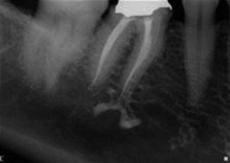
Fig. 10.2
An example of alveolar space. The endodontist has used calcium hydroxide as an interim treatment. During the process of placing this into the root canal system, some has been extruded. Note the radiopacity in areas of the alveolar spaces that were previously occupied by marrow space
The ability to assess the status of implants at any stage is important, and apart from routine monitoring it should be considered a prerequisite to know and record the health status prior to reconstruction, at the commencement of a restoration, or when a replacement prosthesis is being considered. Radiographs can also provide a baseline standard against which subsequent radiographs can be compared to monitor changes over time, provided there is adherence to some form of standardization (Fig. 10.3).
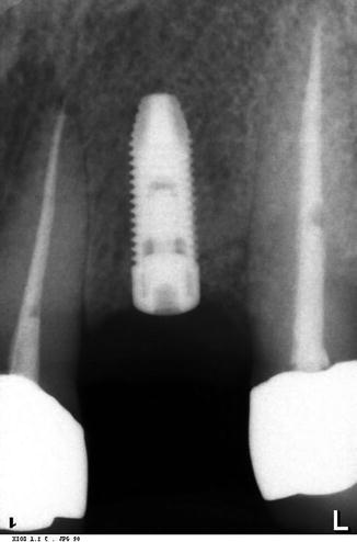
Fig. 10.3
This radiograph was made prior to the commencement of the final restoration. It provides some information about possible pathological issues, the type of bone, how deep the implant is placed, and potential angulation issues with adjacent teeth. It can also be used as a reference to compare future serial radiographs against to evaluate long-term changes, provided they are all standardized
Marginal bone height around implants has been used as a measure for monitoring bone health. Again, in vitro studies have reported on potential errors, suggesting in clinical cases distortion of buccal and lingual bone margins may result in an overestimation of bone heights. The degree of overestimation is influenced by the buccolingual position of the implant. Again, even given these limitations, it is advised that a baseline record should be made with an exacting technique that controls for factors such as position and angulation relative to the implant position prior to the fabrication of a new or replacement restoration.
Mechanical Connection of Implant Components
Visual examination may be possible if the implant head connection to the impression coping is above or very near the free gingival margin. If not, tactile perception may be considered, but a radiograph made with the correct angulation may provide the most useful data.
Periapical radiographs can be a useful adjunct to determine the accuracy of fit for a prosthesis. They provide high-dimensional accuracy, image detail, and minimal magnification and distortion when they are made correctly. To utilize the advantage of intraoral radiography, it is absolutely critical to maintain the X-ray beam perpendicular to the implant’s component connection junction (CCJ). The component connection can be at the crown–abutment junction or abutment–fixture junction. When the proper long-cone paralleling technique is adopted, they offer significant diagnostic value for the dentists and minimal negative health impact on the patients. Inadequate fit of components may result in failure of the prosthesis and the retaining screws connecting the implants to the superstructure and may also have the potential to cause implant-to-bone changes (Fig. 10.4).
Fig. 10.4
The restoration was placed on an implant, which trapped tissue between the implant body and abutment (CCJ). Once the tissue was released, the inflammation resolved. Follow-up revealed no further lesions
Proper radiographs can help clinicians evaluate the fit at the CCJ, but improper alignment between the fixture and the X-ray beam could result in not detecting a misfit and mislead clinicians about the true fit of the implant components. Radiographically detectable edges of the abutment and head of fixture become smaller as the divergence of the X-ray beam increases. Laboratory studies have also confirmed that as the angulation of the X-ray tube diverges away from the angle perpendicular to a restorative margin or the long axis of the implant fixture, identifying misfit becomes increasingly difficult. A model was fabricated with an implant and a spacer providing a gap of 100 μm with the healing cap. Radiographs were made at 0° (orthogonal), 10°, 20°, and 30°. The radiographs produced are seen in Fig. 10.5a–g.
Fig. 10.5
(a–g) These radiographs were made by altering the X-ray cone relative to the implant and healing abutment by (d) 0°, (e)10°, (f) 20°, and (g) 30°. They show how minor errors in angulation alter the ability to detect component fit
The angulation of the X-ray tube head relative to the implant long axis is critical. Under optimum conditions, gaps of 0.05 mm may be detectable, but become obscured when deviations of the X-ray tube head are 5° or more to the long axis of the implant. Gaps of 0.1 mm or larger can also be detected with 10–15° X-ray beam incidence away from the long axis. However, when the incident beam is greater than 10–15°, as seen in Fig. 10.5e, f, these gaps also become obscured. Other factors that also alter the ability to detect gaps include radiographic focal spot size and Focus film distance (FFD). This is the distance between the X-ray source and the film or sensor receptor in diagnostic radiography.
If the goal of treatment is to determine exacting component fit, then clearly the tube angulation must be strictly controlled. This becomes more of a challenge when restorations are splined (Fig. 10.6a, b). The fit of a splinted restoration on implants or a fixed partial denture may present with particular issues related to non-passive fit. Laboratory processes, along with embedment relaxation effects that occur when metal components are connected with screw joints, make multiple implant connection particularly susceptible to non-passive fit errors. When evaluating the seating of such a prosthesis, the individual implant positions must be accounted for with each attachment site (Fig. 10.7a, b).
Fig. 10.6
(a, b) Radiograph at metal try-in appointment. Enlarged image shows intimate contact of both abutments with the implants
Fig. 10.7
(a, b) On final delivery, an orthogonal radiograph indicates a misfit on the left central implant. The prosthesis was remade
It is clear that in evaluating for the fit of implant components, the radiographic image is subject to distortions as a result of angulation effects. Several studies have evaluated these artifacts and how they develop, assessing the relative angulations of X-ray tube, implant body angle, and film or image sensor angulation. The findings from these investigations suggest the following: determine the angle of the implant with respect to the surrounding occlusal plane prior to radiographing, if possible (Fig. 10.8a, b).
Fig. 10.8
(a) It is important to access the implant with respect to radiographic techniques. This implant is angled toward the midline, which must be taken into account when making radiographs. (b) Now restored, the underlying implant’s orientation can only be guessed at
However, if the implant has been previously restored, it may be more difficult to determine the orientation without first removing the restoration. The angulation of the X-ray tube head relative to the implant long axis is critical. If the goal of treatment is to determine exacting component fit, then clearly the tube angulation must be strictly controlled. In the horizontal plane, if the incident X-rays are perpendicular to the long axis of the implant (orthogonal), the mesial and distal tube head angulations are not critical as long as the gap size is uniform; it will be detected from any angle. As a result of this information it is suggested that, given a knowledge of the implant angulation, the tube head orientation in the vertical plane is most critical. To standardize sequential radiographs, a paralleling device may be of use, for example, RINN systems (Dentsply Rinn, Elgin, IL USA). However, the holder should be orientated relative to the implant long axis rather than the occlusal surfaces, which more commonly occurs and produces information that may be inaccurate.
Stay updated, free dental videos. Join our Telegram channel
VIDEdental - Online dental courses


