Introduction
Recent studies have shown that therapeutic loads applied to individual teeth by aligners may substantially exceed recommended values. The primary purpose of this study was to quantify force and moment components during derotation of a maxillary central incisor when 0.3-mm-thick or 0.4-mm-thick polyethylene terephthalate glycol aligners were used instead of conventional polyethylene terephthalate glycol aligners with a minimum thickness of 0.5 mm.
Methods
The test setup consisted of an acrylic model of a maxilla with a separated right central incisor mounted on a 3-dimensional force and moment sensor. The force and moment components were recorded for aligners with thicknesses ranging from 0.3 to 0.75 mm during ±10° rotation and derotation of the separated incisor.
Results
Moments exerted by the thinnest aligner currently available, 0.5 mm, were 73.57 Nmm for the 10° mesiorotation. In comparison, the corresponding moments with the 0.4-mm and 0.3-mm aligners were 41.08 and 17.84 Nmm, respectively. Moment values for derotation of the maxillary right central incisor into neutral position showed nonlinear return curves indicating viscoelastic material behavior.
Conclusions
A significant load reduction can be achieved with the new thinner aligners. Because of the form instability of the 0.3-mm aligner during handling, we suggest the novel sequence 0.4, 0.5, and 0.75 mm for aligner systems based on sequentially increased material thickness. This sequence combines sufficiently low initial aligner stiffness and steady load increases in single setup steps. The viscoelastic behavior of polyethylene terephthalate glycol aligners observed during incisor derotation should lead to a reduction of the high initial load exerted directly after intraoral aligner insertion.
Highlights
- •
Forces and moments applied even by the thinnest aligners are relatively high.
- •
New, thin levelling aligner sequence is proposed to reduce risk of root resorption.
- •
Aligners made of 0.3-mm PET-G foils deformed irreversibly during handling.
- •
Aligners made of 0.4 mm PET-G-aligner were sufficiently stable.
- •
Proposed aligner sequence combines low stiffness and nearly equal load increases.
- •
Different collateral forces and moments occur during central incisor derotation.
In the last 2 decades, new aligner systems using CAD/CAM methods for part or all of the design and fabrication process have been introduced to orthodontics. These systems are usually based on 2 fundamentally different concepts. In the more recently developed approach, setup steps are minimized to values of 0.2 mm or less so that stiffer aligners of uniform thickness can be used. Usually, only 1 initial impression must be taken during treatment due to the implementation of digital setups and stereolithographic models. In the second approach, malpositioned teeth are corrected in larger steps with relative tooth displacements between 0.5 and 1 mm. To maintain the force and moment values applied to the teeth at an appropriate force level during ongoing alignment, the latter approach uses a sequence of 3 aligners with increasing thickness per setup step. In this concept, aligners are usually manufactured in the laboratory of the orthodontist’s practice, either on real stone setup models or on 3-dimensional (3D) prints of digital setups. This may lead to better monitoring and control of the procedure by the clinician and reduce or avoid external laboratory costs. The manual setup procedure includes segmentation of the individual teeth and stepwise movement of selected teeth toward their desired positions, supported by model superimpositions, digital measurements, and thermoforming of aligners for each treatment step. Three aligners with increasing thicknesses of 0.5, 0.625, and 0.75 mm are recommended in this approach.
A review of available literature for techniques using real setup models showed that guidelines for both the “optimum” movement ranges of single teeth in each treatment step and selection of thermoplastic foil thickness are rather empirical and have not been sufficiently and systematically evaluated. A few studies have characterized the stiffness of aligners by use of 3-point bending tests with flat specimens prepared from plastic sheet. Ryokawa et al examined the forces applied by 8 different aligner specimens under simulated intraoral conditions and the thickness changes after thermoforming and water absorption. Thickness reduction because of thermoforming from 7.4% to 25.1% and thickness increase after water absorption from 100.3% to 119.9% were observed. Reduced aligner fit because of hygroscopic expansion of the aligner was also reported. Kwon et al investigated the force-delivery properties of 3 different thermoplastic orthodontic materials of thicknesses between 0.5 and 1.0 mm by using 3-point bending tests and material specimens thermoformed on a flat plaster model to simulate the thermoforming process. They concluded that for avoiding excessive force to teeth, the setup increments should range from 0.2 to 0.5 mm, depending on the type of material used. Although such 3-point bending and mechanical tests of flat thermoplastic specimens enable basic comparisons between different materials and conclusions on factors that affect the results, they cannot be regarded as realistic tests in respect of the loads applied to individual teeth in the clinic. This is primarily because of changes in the geometric shape of aligners after thermoforming on models of a complete dentition, which are supposed to reinforce the aligner material and lead to a significant increase in the forces and moments applied to the teeth.
Other in-vitro studies have investigated the force and moment (F/M) application of aligners for simulated tooth movement in a more realistic setup using a model of a whole jaw. In a series of studies, loads applied to a maxillary central incisor during experimental labiopalatal tipping, torquing, translation, and mesiodistal rotational movement were examined. During mesiodistal rotation of ±7.5°, moments of up to −71.8 Nmm were measured, exceeding the appropriate load of approximately 20 Nmm by a factor of 3.6. Surprisingly high collateral intrusive forces of up to −5.8 N were also observed, indicating overloading of this F/M component also. Similar results were obtained for other types of tooth movement, including translation, tipping, and torquing of 1 measurement tooth. Another aspect that has been reported is the effect of occlusal forces, leading to load increases by a factor of up to 3.5 for rotational moments and a factor of 18 for intrusive forces. Although these studies indicate the forces and moments applied to individual teeth, they are, to some extent, limited in their in-vitro character and in restricting the determination of only 1 or 2 of the 6 F/M components. Such data do not reflect the complete biomechanical interaction between the aligner and the teeth, jeopardizing full understanding of these complex interrelations.
A few studies have achieved direct measurement of the in-vivo forces applied by aligners to the teeth of patients by using pressure-indicating foil placed between the aligner and the tooth or by using strain gauges to determine the von Mises strains at different times during a 2-week period. Both showed an average force reduction of 51% after a 2-week period of wear; this reduction, which led to deactivation, was related to aligner deterioration in the intraoral environment and to the tooth movement achieved. General disadvantages of such in-vivo studies are related to the pressure measurement in a portion of the tooth crown only, in a situation of uneven pressure distribution. It seems, therefore, impossible to determine the effective load on 1 tooth as a whole. Again, only 1 pressure direction can be recorded; in general, the inaccuracy of this type of measurement is relatively high.
The results from previous studies indicate overloading of teeth when current recommendations for setup steps and aligner materials are followed. Reduction of the forces and moments applied by aligners to individual teeth might, in principle, be achieved either by smaller setup increments or by using thinner, less stiff aligner materials. The purpose of this study was mainly the second approach. More specifically, the 6 F/M components applied by 0.3-mm or 0.4-mm thin aligners to an incisor were determined and compared with the corresponding values for conventional aligners with a thickness of 0.5 mm or greater. We chose mesiodistal derotation of a maxillary central incisor as the experimental movement, because this is a typical treatment task for aligners. In addition to mechanical behavior, the stability of the shape of the thinner aligners after thermoforming and repeated seating on and removal from the test model were also evaluated. Another aspect of the study was to determine which aligner thickness sequence would lead to the most steady moment increase in 1 derotation step on the setup model. Aligners with thicknesses up to 0.75 mm were also included in the study.
Material and methods
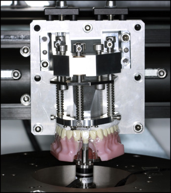
The experimental setup ( Fig 1 ) consisted of a model of a maxilla (Frasaco, Tettnang, Germany) with the maxillary right central incisor separated. This “measurement tooth” was mounted via a 3D F/M sensor (Nano 17 Sensor; ATI Industrial Automation, Apex, NC) on a hexapod (PI M-850; Physik Instrumente, Karlsruhe, Germany). The hexapod can be regarded as a robot enabling 3D translation and rotation for simulation of different malpositions of the measurement tooth. A horseshoe-shaped aluminum plate, the lower surface of which was lined with dental silicone rubber, was used to simulate occlusal forces of 30 N in total. These forces guaranteed reproducible positioning of the aligner on the model and prevented the aligner from being dislodged from the model during the experiment. The whole test apparatus was enclosed in a specially constructed climate chamber to maintain a temperature of 37°C.
Polyethylene terephthalate glycol (PET-G) aligners (Duran; Scheu Dental, Iserlohn, Germany) were thermoformed from commercially available 0.5-mm, 0.625-mm, and 0.75-mm thick foils; additional aligners made of the same thermoplastic material but of lower thickness, 0.3 mm and 0.4 mm, were also tested. An impression of the Frasaco model was taken before separating the maxillary central incisor from the model. The corresponding plaster cast model was duplicated 10 times with type 4 dental cast stone (Fujirock; GC Europe, Leuven, Belgium). Two lines were drawn on each cast model; these marked the embedding depth in the thermoforming machine, about 10 mm, measured from the gingival margins, and the gingival extension of the aligners, 3 mm, from the same reference. All aligners were thermoformed in accordance with the manufacturer’s recommendation ( Table I ). After thermoforming, the line marking the gingival depth was transferred to the aligners, which were then cut to this mark. Three aligners were fabricated from foils of each thickness.
| Aligner | Foil thickness (mm) | Use of spacer foil (Isofolan) | Heating time (sec) | Cooling time (sec) |
|---|---|---|---|---|
| Duran | 0.3 | Yes | 20 | 20 |
| 0.4 | Yes | 20 | 20 | |
| 0.5 | Yes | 25 | 20 | |
| 0.625 | Yes | 25 | 60 | |
| 0.75 | Yes | 25 | 60 |
Before measurement, each aligner was stored for at least 30 minutes in the climate chamber to attain a temperature of 37°C. The aligners were then moistened with artificial saliva (Glandosane; Cell Pharm, Bad Vilbel, Germany) and seated on the test model with the maxillary central incisor in a neutral position corresponding to its position before separation from the model. The horseshoe plate simulating the occlusal forces from the maxilla was seated, and the screws were tightened to exert 30 N. Mesiodistal rotation of the measurement tooth in both directions, with a maximum range of 10° in 0.25° increments, was simulated. The movement cycles started in the neutral position and were followed by incremental 10° mesiorotation, derotation to the neutral position, distorotation, and then derotation to return to the neutral position. Each cycle was repeated 3 times with the same aligner.
Statistical analysis
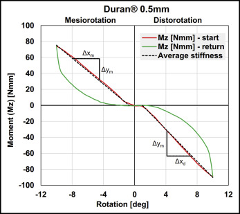
Collected data were analyzed with special algorithms written in Matlab (MathWorks, Natick, Mass). Descriptive data analysis included calculation of maximum, minimum, and median values and quartiles of the 6 F/M components applied to the measurement tooth in each movement step. Due to their linear behavior ( Fig 2 ), the start curves of the mesiorotation and distorotation were characterized by calculating the stiffness values for the corresponding aligner and rotational direction. These values were obtained by determining the slope for each pair of subsequent data points and averaging the corresponding 5th to 95th percentiles. The return curves showed a nonlinear course. Hence, moment values for different degrees of derotation were determined.
The calculated rotational stiffness was evaluated statistically with SAS software (version 9.1.3; SAS Institute, Cary, NC). A Kruskal-Wallis test was performed to determine the correlation of rotational stiffness with aligner thickness and any direction-dependent pattern. The linearity values of the rotational stiffness increase for the conventional aligner sequence (0.5, 0.625, and 0.75 mm) and that for the new possible sequences including the thinner aligners were also analyzed by calculation of the corresponding Pearson correlation coefficients (ρ).
Results
Figure 2 exemplifies the curve for mesiodistal rotational moments (Mz) measured during the ±10° rotation and derotation of the maxillary central incisor in both directions with the 0.5-mm aligner. Starting from the neutral position, increasing mesiorotation or distorotation of the incisor led to nearly linear increases of the absolute Mz values. For this aligner thickness, Mz reached values of 73.57 Nmm for 10° mesiorotation and −89.19 Nmm for 10° distorotation ( Table II ). In comparison, corresponding moments for the thinner 0.4-mm and 0.3-mm aligners, respectively, were 41.08 and 17.48 Nmm for mesiorotation and −48.41 and −21.67 Nmm for distorotation. When compared with the maximum rotational moments for the 0.5-mm aligner, these values corresponded to reductions of 45% (0.4-mm aligners) and 76% (0.3-mm aligners).
| Aligner | Direction | Foil thickness (mm) | Mesiodistal rotational moment (Nmm) | IQR for rotational moment | Intrusive force (Fz) | IQR for intrusive force |
|---|---|---|---|---|---|---|
| Duran | Mesiorotation | 0.3 | 17.48 | 5.72 | −3.58 | 0.82 |
| 0.4 | 41.08 | 23.77 | −7.54 | 3.93 | ||
| 0.5 | 73.57 | 2.42 | −12.76 | 0.39 | ||
| 0.625 | 84.20 | 3.93 | −15.02 | 1.16 | ||
| 0.75 | 91.58 | 2.53 | −16.96 | 0.58 | ||
| Distorotation | 0.3 | −21.67 | 4.19 | −3.65 | 0.57 | |
| 0.4 | −48.41 | 26.87 | −7.13 | 3.54 | ||
| 0.5 | −89.19 | 3.06 | −12.86 | 0.23 | ||
| 0.625 | −112.67 | 6.26 | −16.18 | 0.81 | ||
| 0.75 | −136.13 | 22.73 | −19.70 | 1.90 |
The stiffness values determined for the nearly linear start curves for experimental mesiorotation and distorotation are given in Table III and illustrated in Figure 3 . As indicated by the high correlation coefficient of 0.9, increasing aligner thickness is positively correlated with the stiffness. Hence, the highest stiffness values were observed for the 0.75-mm aligner with values up to 9.95 Nmm per degree for mesiorotation and 13.88 Nmm per degree for distorotation. Percentage increases from the thinnest to the thickest aligners indicated that stiffness differences between the 0.5-mm and 0.625-mm, as well as the 0.625-mm and 0.75-mm aligners, were relatively small. According to the Pearson correlation coefficients (ρ), omitting the 0.625-mm aligner and including a 0.4-mm or 0.3-mm aligner instead substantially increased the linearity of the stiffness increments in an aligner sequence ( Table IV ).
Stay updated, free dental videos. Join our Telegram channel
VIDEdental - Online dental courses


