Introduction
The miniscrew has been developed and effectively used as orthodontic anchorage, but current studies of its usage are insufficient to provide information about the underlying mechanical mechanisms. The aim of this study was to investigate the roles of bone quality, loading conditions, screw effects, and implanted depth on the biomechanics of an orthodontic miniscrew system by using finite element analysis.
Methods
A 3-dimensional model with a bone block integrated with a miniscrew was constructed to simulate various cortex thicknesses, cancellous bone densities, force magnitudes and directions, screw diameters and lengths, and implanted depths of miniscrews.
Results
Both stress and displacement increased with decreasing cortex thickness, whereas cancellous bone density played a minor role in the mechanical response. These 2 indexes were linearly proportional to the force magnitude and produced the highest values when the force was perpendicular to the long axis of the miniscrew. A wider screw provided superior mechanical advantages. The exposed length of the miniscrew was the real factor affecting mechanical performance.
Conclusions
The screw diameter was the dominant factor for minscrew mechanical responses. Both bone stress and screw displacement decreased with increasing screw diameter and cortex thickness, and decreasing exposed length of the screw, force magnitude, and oblique loading direction.
Anchorage control plays a crucial role in orthodontic treatment. It can maximize desired tooth movement and minimize undesired side effects. To obtain stronger anchorage, the orthodontic miniscrew was developed and has been used effectively as orthodontic anchorage for various types of tooth movement. Compared with conventional dental implants used for orthodontic anchorage, the orthodontic miniscrew, as a temporary mini-implant, offers many advantages, such as easier surgical procedure, less trauma during insertion and removal, minimal anatomic limitations, immediate loading after implantation, and lower costs. However, some clinical studies have reported a relatively high failure rate in miniscrews used for orthodontic anchorage. Factors identified as causing failure include inflammation, infection, nonkeratinized implant sites, and small miniscrews.
Because of the nature of the orthodontic miniscrew, load transfer, and small size, biomechanical factors have been investigated in many studies. Previous studies have evaluated the stability of miniscrew anchorage systems with mechanical experiments, histomorphometric studies, and finite element simulations of the roles of screw geometry, bone quality, implantation conditions, and loading effects. Many suggestions were provided to increase the stability, such as using conical-shaped screws, including abutment, preventing cervical threading, using screws with a wide diameter, applying screws with a length of 9 mm, achieving bicortical or partial osseointegration, implanting in cortical bone more than 1-mm thick, mplanting in high-density bone, exploiting drill-free miniscrews, insertion with 60° to 70° of angulation, securing with 5 to 10 Ncm insertion torque, and tilting the load in a buccal direction. However, most of these suggestions were provided without the support of mechanical reasoning. These outcomes could depend on the model or method and should be applied with caution. Without a thorough understanding of the biomechanical rationale of the orthodontic miniscrew, no reliable guidelines can be provided for its clinical usage. The aim of this study was therefore to investigate the roles of bone quality, loading conditions, screw size, and implanted depth on orthodontic miniscrews by using finite element analysis. The hypothesis was that, with the full field of mechanical responses and the precise control of parameters in finite element analysis, it is possible to determine the underlying biomechanical mechanism of miniscrews and thus provide reliable usage guidelines.
Material and methods
A 3-dimensional bone block model integrated with a miniscrew was constructed with a computer-aided design program (SolidWorks; Dassault Systèmes SolidWorks, Concord, Mass) to simulate a miniscrew implanted in bone as an orthodontic anchorage unit. The bone block, consisting of cortical and cancellous bones, was simplified to dimensions of 20 mm in length and width, and 15 mm in height for evaluation. The miniscrew geometry was based on the MONDEAL system (MONDEAL Medical Systems, Muhlheim, Germany): ie, the screw thread profile was an isosceles triangle 0.4 mm in height and 0.16 mm along the base ( Fig 1 , A ). The thread pitch was 1.0 mm. These thread dimensions were fixed in all screw designs in this study. The model was meshed automatically with 10-node tetrahedral solid elements ( Fig 1 , B ). The interface between the cortex and the cancellous bone was assumed to be fully bonded; ie, the elements were continuous, sharing the same nodes along the interface. A node-to-node contact condition was given on the interface between the miniscrew and the bone block to imitate a stage without osseointergration.
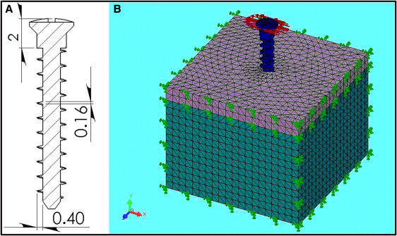
All materials in the model were homogeneous, isotropic, and linearly elastic. The miniscrew was assumed to be pure titanium with a Young’s modulus of 110 GPa and a Poisson’s ratio of 0.35. For healthy bone quality, the Young’s moduli of the cortical and cancellous bones were 14 GPa and 1.3 GPa, respectively, and the Poisson’s ratios were 0.3 for both. The static load along the x-axis was applied to the head of the miniscrew and perpendicular to its long axis to simulate the orthodontic force. For the nodes located on the 5 exterior surfaces of the bone block, all but the superior surface where the miniscrew entered was constrained in all degrees of freedom to simulate the boundary condition ( Fig 1 , B ). The nodal solution of the von Mises stress in the bone and the displacement of the miniscrew were calculated for each model with the finite element analysis program.
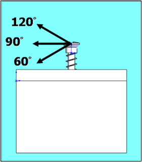
To justify the effect of bone quality on stress generation, 4 cortex thicknesses—0.5, 1.2, 2.0, and 3.0 mm—and 4 types of cancellous bone density with values that were normal and 1/2, 1/4, and 1/8 of Young’s modulus (1.3 GPa, and 650, 325, and 162.5 Mpa) of normal cancellous bone were studied. To determine the loading effect, 3 force magnitudes (2, 4, and 6 N) and force directions (60°, 90° and 120°) to mimic various clinical conditions were investigated. Force direction was defined as the angle between the loading direction and the long axis of the miniscrew, and a force direction of 90° was the force perpendicular to the long axis of the miniscrew ( Fig 2 ).
To determine the screw size effect, 3 screw (outer) diameters (1.2, 1.5, and 2.0 mm) and 5 screw lengths (7-15 mm at 2-mm intervals) were investigated. The screw length was measured including the screw head, which had a 2-mm height for all screw models. To provide information on how deep a screw should be implanted, various screw depths (screw length in the bone block) were modeled. For each screw length, the implanted depth started at 2 mm and increased in 2-mm increments until the exposed screw length (screw segment above the bone block) was 3 mm (including the screw head). For instance, the model with a 13-mm screw length would be implanted in the bone block at 2, 4, 6, 8, and 10 mm.
Results
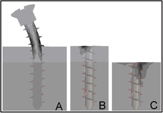
Figure 3 shows the peak von Mises stress on the miniscrew and the surrounding bone under 2 N, 90° force. Both compressive and tensile stresses were identified on 2 sides of the miniscrew, and the peak von Mises stress on the miniscrew was concentrated near the entrance point to the cortical bone, which represented a pivot point of the bending ( Fig 3 , A ). For cortical bone, the peak stress was located on the compression side of the entrance point because of the contact between the miniscrew and the cortex ( Fig 3 , B ). The peak stress on cancellous bone was concentrated, again, at the entrance point of the miniscrew, but this time on the screw’s tensile side, because of the seesaw effect ( Fig 3 , C ).
In general, the stress induced on cancellous bone is much lower than that on the cortex. In addition, the most commonly identified structure failure in miniscrew anchorage systems is screw loosening. Therefore, only cortex stress was examined in this study. The maximum displacement was always located at the top of the miniscrew head in all models and also evaluated for stability justification. For comparison among various factors in the following analyses, a bone model with a cortex thickness of 2 mm and a normal cancellous bone density implanted with a miniscrew 2 mm in diameter and 13 mm in length embedded at a depth of 8 mm under 2 N, 90° loading was defined as the base model. The result from the base model was set as 1, and the resulting data were expressed as ratios of values to the base model in the following figures.
The peak von Mises stress on the cortex increased as the cortex thickness decreased from 3.0 to 0.5 mm under the same loading conditions. However, these stress increases were mild, less than 10%, except when the cortex thickness was reduced from 1.2 to 0.5 mm, which induced a significant stress increase of 20% to 25% for different densities of cancellous bone. On the other hand, the density of the cancellous bone had a minor effect on the cortex bone stress, no matter how thick the cortex was. Coupling these 2 bone factors, cortex thickness and cancellous bone density, comparisons of the peak von Mises stress on the cortex are summarized in Figure 4 , A . In the base model, when the Young’s modulus of cancellous bone was reduced to one eighth of normal, the peak von Mises stress on the cortex increased by only 3%. However, if the cortex thickness and Young’s modulus of cancellous bone were reduced simultaneously to 0.5 mm and one eighth of normal, respectively, the peak von Mises stress increased by 34%.
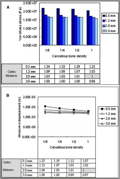
The maximum displacement, occurring at the miniscrew head as stated above, was always located at the top of the miniscrew head in all models under all loading conditions. The tendencies of maximum displacement of the miniscrews related to cortex thickness and cancellous bone density were similar to the results of the peak von Mises stresses on the cortex. The displacement results of the coupling effects of cortex thickness and cancellous bone density are summarized in Figure 4 , B . In the base model, when the Young’s modulus of cancellous bone decreased to one eighth of normal, the maximum displacement of the miniscrews increased by only 4%. However, if the cortex thickness and the Young’s modulus of cancellous bone were reduced simultaneously to 0.5 mm and one eighth of normal, respectively, the maximum displacement of the miniscrew increased by 27%.
Increasing the force magnitude resulted in a higher peak von Mises stress on the cortex, and the peak stress was linearly proportional to the force magnitude. A force direction of 90° showed a higher peak von Mises stress than force directions of 60° and 120°, and the peak von Mises stress values for 60° and 120° were almost the same. If the peak von Mises stress value from the base model was set as 1, those from force directions of 60° and 120° decreased by 13% and 15%, respectively. Figure 5 , A , summarizes the effects of force factors on the peak von Mises stress on the cortex.
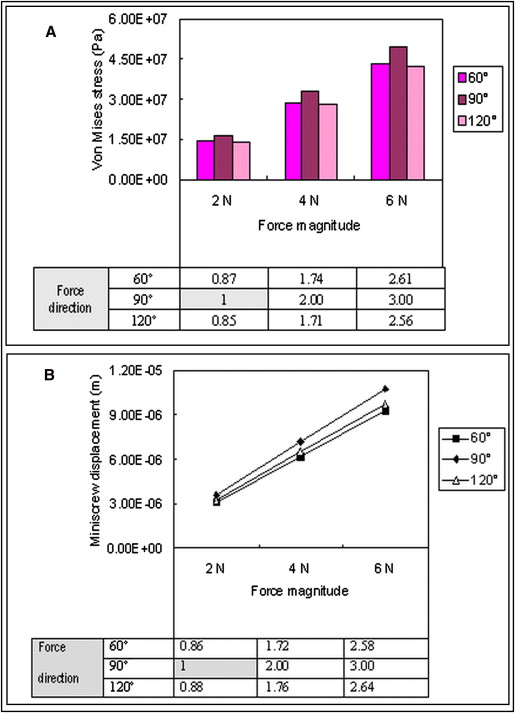
The results of the force effects related to the maximum displacement of the miniscrews were also similar to the results from the peak von Mises stress on the cortex. Increasing the force magnitude resulted in greater displacement of the miniscrew, and the maximum displacement of the miniscrews was also linearly proportional to the force magnitude. A force direction of 90° showed the highest maximum displacement in the miniscrews, whereas the values from 60° and 120° were almost same. If the maximum displacement from the base model was set as 1, those from force directions of 60° and 120° decreased by 14% and 12%, respectively. Figure 5 , B , shows the force effects on maximum miniscrew displacement.
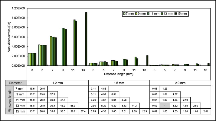
The miniscrew size and implanted depth effects on the maximum von Mises stress of the cortex were also examined. The maximum von Mises stress on the cortex increased significantly as the diameter of the miniscrew decreased. For example, as the miniscrew diameter decreased from 2.0 to 1.2 mm, the maximum von Mises stress increased more than 30 times. With the same miniscrew, the maximum von Mises stress on the cortex decreased as the implanted depth increased. But as the implant length increased, under the same implanted depth, the maximum von Mises stress on the cortex increased. Close examination of the results showed that the exposed screw length (screw length above the cortex or total screw length minus the implanted depth) was the dominant factor. For the same screw diameter, the von Mises stress was almost the same when the exposed screw length was the same, no matter how long the screw was and how deep the screw was implanted. To give an overview of the results of miniscrew effects, the maximum von Mises stress values on the cortex were plotted against the miniscrew diameter, length, and exposed length, as shown in Figure 6 . The trend of the maximum displacement of the miniscrew related to the miniscrew effects was similar to that of the maximum von Mises stress in bone related to the miniscrew effects.