Learning Objectives
After reading this chapter, the student should be able to:
- 1.
Describe the importance of radiographs in endodontic diagnosis, treatment, and postoperative evaluation.
- 2.
Discuss special applications of radiography to endodontics.
- 3.
Discuss reasons for limiting the number of exposures.
- 4.
Identify normal anatomic features in the maxilla and mandible on radiographs.
- 5.
Describe radiographic characteristics to differentiate between endodontic and nonendodontic (normal and pathologic) radiolucencies and radiopacities.
- 6.
Describe the reasons for varying horizontal and vertical cone angulations on working radiographs to create image shift.
- 7.
Describe how to determine the third dimension on angled radiographs (i.e., faciolingual structures [SLOB] rule).
- 8.
Describe structural elements of the tooth as visualized on both facial and angled projections.
- 9.
Discuss how to detect the presence of and locate undiscovered canals or roots on angled working radiographs.
- 10.
Describe techniques for making “working” radiographs (i.e., film/sensor placement and cone alignment with dental dam in place).
- 11.
Describe specific details of film/sensor placement and cone alignment for each tooth on working radiographs.
- 12.
Describe the limitations of rapid processing of working films.
- 13.
Describe the radiographic technique for locating a “calcified” canal.
- 14.
Discuss the limitations of radiographic interpretation.
- 15.
Describe some new technologies and their application to endodontic radiography now and in the future.
- 16.
Describe the technique for extraoral positioning of the film and cone.
- 17.
Describe the specific indications of cone beam computed tomography (CBCT) in endodontics.
We are sick of the roentgen ray . . .you can see other people’s bones with the naked eye, and also see through eight inches of solid wood. On the revolting indecency of this there is no need to dwell. But what we seriously put before the attention of the Government . . .that it will call for legislative restriction of the severest kind. Perhaps the best thing would be for all civilized nations to combine to burn all works on the roentgen rays, to execute all the discoverers, and to corner all the tungstate in the world and whelm it in the middle of the ocean. Editorial in the Pall Mall Gazette, London, 1896
Obviously (and fortunately), the concern expressed by the editorial in this London publication did not become the popular view of radiography. Radiographs are essential; they are a second set of “eyes” for the dentist. This is particularly true in endodontics, in which so many diagnostic and treatment decisions are based on radiographic findings. Because most structures of concern are not visible to the naked eye, there is considerable dependence on radiographs, which are an obvious necessity and a blessing. But they also may be somewhat of a liability from the standpoint of both safety and time, and unfortunately, radiographs are often overinterpreted or underinterpreted.
A radiographic exposure is an irreversible procedure; therefore, only necessary exposures should be made. With the increasing emphasis and justifiable concern for radiation safety, overall radiation exposure must be minimized. However, the radiation dosage to oral and other tissues has been calculated to be very low and to cause minimal (but some) risk.
Another concern is the time required to make and process individual radiographs—time is money. Therefore, in the interests of both safety and time, only the radiographs necessitated by the procedure should be made.
This chapter discusses radiography as applied to endodontic procedures. Radiography as a discipline in dentistry has become increasingly important with advances in technology and has recently been granted specialty status, thereby replacing endodontics as the youngest dental specialty. Technology has exploded in recent years, with new devices and approaches that require special training and experience. How these new devices and approaches apply to diagnosis and treatment in endodontics is discussed later in this chapter.
Importance of Radiography in Endodontics
Radiographs perform essential functions in three areas: diagnosis, treatment, and postoperative evaluation or follow-up. Each of these has limitations that require its own special approach. A single radiograph is but a two-dimensional shadow of a three-dimensional (3D) object. For maximum information, the third dimension must be visualized and interpreted. The advent of 3D radiographic techniques, such as CBCT (discussed later in the chapter), has highlighted this concept.
Digital Radiography
The use of digital radiography is becoming more common in dentistry. Although there are technical advantages over conventional approaches, the same limitations apply. Overall, digital radiographs are equivalent to conventional radiographs with regard to diagnostic and treatment-related accuracy. These factors and other considerations are discussed further throughout this chapter.
Diagnosis
Diagnostic radiology involves not only identifying the presence and nature of pathosis, but also determining root and pulp anatomy and characterizing and differentiating other normal structures.
Identifying Pathosis
Radiographs must be studied carefully by someone with a working knowledge of the changes that indicate pulpal, periapical, periodontal, or other bony lesions. Many changes are obvious, but some are subtle.
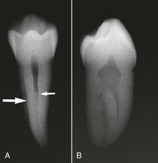
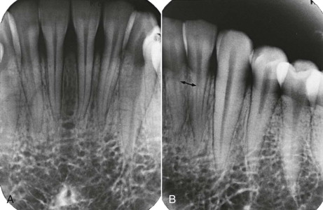
Determining Root and Pulpal Anatomy
Determining the anatomy involves not only identifying and counting the roots and canals, but also identifying unusual tooth anatomy, such as dens invaginatus and a C -shaped configuration, and determining curvatures, canal relationships, and canal location. Identification also includes characterizing the cross-sectional anatomy of individual roots and canals ( Fig. 12.1 ).
Characterizing Normal Structures
Numerous radiolucent and radiopaque structures often lie in close proximity. Frequently, these structures are superimposed over and obscure crowns and roots. These must be distinguished and differentiated from pathosis and from normal dental structures.
Treatment
“Working” radiographs are made while the dental dam is in place, which creates problems in film placement and cone positioning. These radiographs are exposed during the treatment phase and have special applications.
Determining Working Lengths
The distance from a reference point to the radiographic apex is determined precisely. This establishes the distance from the apex at which the canal is to be prepared and obturated.
Moving Superimposed Structures
Radiopaque anatomic structures often overlie and obscure roots and apices. Using special cone angulations, these radiopaque structures can be “moved” to give a clear image of the apex.
Locating Canals
Canal location is obviously essential to success. Standard and special techniques allow the practitioner to determine the position of canals not located during access.
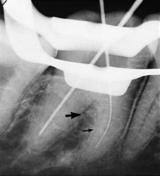
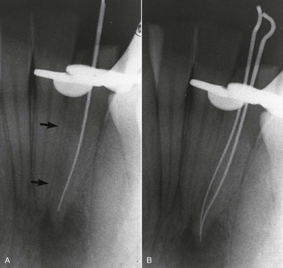
Differentiating Canals and Periodontal Ligament Spaces
Canals end in the chamber and at the apex. A periodontal ligament space ends on a surface and in a furcation (molars) and demonstrates an adjacent lamina dura ( Fig. 12.2 ).
Evaluating Obturation
Postoperative radiographs provide considerable information on canal preparation and obturation. The length from the apex, density, taper, preservation of original canal shape, and general quality of obturation in each canal are determined from these radiographs.
Follow-up Evaluation (Recall)
Ultimate success is verified at specified intervals of months or years after treatment. Because failures often occur without signs or symptoms, radiographs are essential to evaluate periapical status.
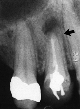
Identifying New Pathosis
The presence and nature of lesions that arise after treatment are best detected on radiographs. These lesions may be periapical, periodontal, or nonendodontic. It is important to remember that such lesions frequently present with no overt signs or symptoms and are detectable only on radiographs ( Fig. 12.3 ).
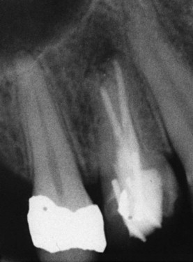
Evaluating Healing
Pretreatment lesions should be resolving or should have resolved. In a successful (healed) treatment, restitution of generally normal structures should be evident on recall radiographs ( Fig. 12.4 ).
Special Applications
Radiographs should be used to their maximum advantage. The following alternative techniques greatly enhance the ability to make an accurate and definitive diagnosis and to control treatment procedures.
Cone-Image Shift
Varying either the vertical or, particularly, the horizontal cone angulation from parallel alters images and enhances interpretation. These shifts reveal the third dimension and superimposed structures. Shifts also permit identification and positioning of objects that lie in the faciolingual plane.
Working Radiographs
Working radiographs are essential aids to treatment and are exposed when necessary but with discretion.
Radiographic Sequence
Radiographs are made in a recommended order and number for each procedure. The minimum number is described here, although special situations may require additional exposures.
Diagnostic Radiographs
Number
The number of exposures depends on the situation. For diagnosis in most cases, only a single exposure is necessary. A properly positioned film and cone (usually a parallel projection is best) permits visualization at least 3 to 4 mm beyond the apex. The initial diagnostic radiograph is used primarily to detect pathosis and to provide general information on root and pulp anatomy. A bitewing radiograph may aid in determining the extent of caries or in detecting caries or an open margin of a crown. Usually, it is not necessary at this time to make additional films for identification of additional canals except in endodontically treated teeth, in which missed canals can be identified by using a shift.
If other films are at hand, each gives a slightly different view of the same tooth ( Fig. 12.5 ). Examine the tooth on each film in which it appears.
Angulation
Unquestionably, the most accurate radiographs are made using a paralleling technique. The advantages are (1) less distortion and more clarity and (2) reproducibility of film and cone placement with preliminary and subsequent radiographs. Reproducibility is important when assessing whether changes occurring in the periapex indicate healing or nonhealing. Paralleling devices enhance reproducibility.
There may be special situations in which the paralleling technique is not feasible, such as a low palatal vault, maxillary tori, exceptionally long roots, or an uncooperative or gagging patient; these circumstances may necessitate an alternative technique. A second choice is the modified paralleling technique; the least accurate technique is the bisecting angle.
Working Radiographs
Special situations require special considerations. Although the basic principles of doing everything possible to obtain the best quality radiograph are followed, there are definite limitations in making working films. These require cooperation by the patient if he or she holds the film or sensor in position.
These radiographs are usually neither parallel nor bisecting angle. The technique used is called modified paralleling. Essentially, the film is not parallel to the tooth, but the central beam is oriented at right angles to the film surface. In endodontic working radiographs, a further modification is made by varying the horizontal cone angle. Specific details of film/sensor and cone placement and radiographic interpretation are discussed later in this chapter.
Working Length
In general, establishment of working length should require only a single exposure. If a root contains or may contain two superimposed canals, either a mesial or distal angle projection is absolutely necessary; the straight facial view is not particularly helpful. Additional working length radiographs may be required later for confirmation of working lengths to detect the presence or lengths of newly discovered canals ( Fig. 12.6 ) or for reexposure if an apex has been cut off in the first radiograph.
Master Cone
The same principles used with working length films apply. With proper technique, only one radiograph is necessary to evaluate the length of the master gutta-percha cone. The master cones should extend to, or very close to, the corrected working length. (Procedures for the fitting of master cones are discussed in Chapter 18 .)
Other Considerations
Additional working radiographs are often required. For example, they are useful as aids in locating a canal or in determining the occurrence of procedural accidents (perforations, separated instruments, or ledges). Variations in cone positioning and angulation are made as required. When there is doubt about the accuracy of the master cone fit, an intermediary fill radiograph may be exposed after the master cone has been condensed with sealer but before the obturation is finalized. Errors in length or density can be corrected at this stage.
Obturation
The same basic principles used for diagnostic radiographs apply. At least a parallel projection should be made. In teeth with multiple canals, it is desirable to supplement this with an angled projection to visualize separate superimposed canals for separate evaluation of each. However, the radiograph gives only a rough indication of obturation length and quality.
Follow-up Evaluation (Recall)
The same principles used for diagnostic and obturation radiographs (parallel projection and exposure factors) apply to recall radiographs. There is one exception. If treatment is deemed to be questionable or a failure, additional angled radiographs are often required to search for a previously undetected canal or other abnormality.
Exposure Considerations
Proper x-ray machine settings and careful film processing are important for maximal quality and interpretative diagnostic and working radiographs. D film (Ultraspeed) and E film (Ektaspeed) have been used and compared. Although D film has been shown to have slightly better contrast, overall suitability is equivalent for the two film types. The newer Ektaspeed Plus film produces an image similar in quality to Ultraspeed film but requires only half the radiation of Ultraspeed.
The optimal setting for maximal contrast between radiopaque and radiolucent structures is 70 kV. Exposure time and milliamperage should be set individually on each machine. Therefore, the preferred film types are E and Ektaspeed Plus to minimize x-ray irradiation at 70 kV and to maximize clarity.
Digital radiographs require much less exposure time than conventional radiographs, which is a definite advantage. In general, there does not appear to be a significant difference in clinical accuracy between conventional and digital radiography or among different digital radiography systems.
Cone-Image Shift
The cone-image shift reveals the third dimension.
Principles
Image Shift
Superimposed Structures
The cone-image shift technique separates and identifies the facial and lingual structures. An example is the mesiobuccal root of a maxillary molar that contains two superimposed canals. The cone shift separates and permits visualization of both canals.
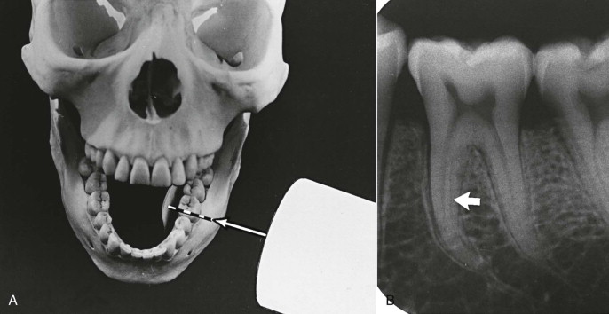
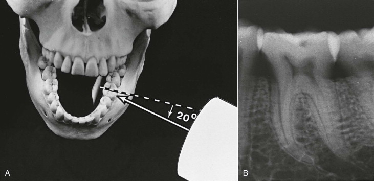
Faciolingual Determination
Principles of relative movement of structures and film orientation are applied to the differentiation of object position ( Figs. 12.7 and 12.8 ).
SLOB Rule
When two objects and the film or sensor are in a fixed position buccal and lingual from each other, and the radiation source (cone) is moved in a horizontal or vertical direction, images of the two objects move in the opposite direction ( Fig. 12.9 ). The facial (buccal) object shifts farthest away; the lingual object moves in the direction of the cone movement. The resulting radiograph shows a lingual object that moved relatively in the same direction as the cone and a buccal object that moved in the opposite direction. This principle is the origin of the acronym SLOB (same lingual, opposite buccal).
Stay updated, free dental videos. Join our Telegram channel
VIDEdental - Online dental courses


