Introduction
The aim of this prospective study was to use cone-beam computed tomography to assess the dimensional changes of the upper airway in orthodontic patients with maxillary constriction treated by rapid maxillary expansion.
Methods
Fourteen orthodontic patients (mean age, 12.9 years; range, 9.7-16 years) were recruited. The patients with posterior crossbite and constricted maxilla were treated with rapid maxillary expansion as the initial part of their comprehensive orthodontic treatments. Before and after rapid maxillary expansion cone-beam computed tomography scans were taken to measure the retropalatal and retroglossal airway changes in terms of volume, and sagittal and cross-sectional areas. The transverse expansions by rapid maxillary expansion were assessed between the midlingual alveolar bone plates at the maxillary first molar and first premolar levels. The measurements of the before and after rapid maxillary expansion scans were compared by using paired t tests with the Bonferroni adjustment for multiple comparisons.
Results
After rapid maxillary expansion, significant and equal amounts of 4.8 mm of expansion were observed at the first molar ( P = 0.0000) and the first premolar ( P = 0.0000) levels. The width increase at the first premolar level (20.0%) was significantly greater than that at the first molar level (15.0%) ( P = 0.035). As the primary outcome variable, the cross-sectional airway measured from the posterior nasal spine to basion level was the only parameter showing a significant increase of 99.4 mm 2 (59.6%) after rapid maxillary expansion ( P = 0.0004).
Conclusions
These results confirm the findings of previous studies of the effect of rapid maxillary expansion on the maxilla. Additionally, we found that only the cross-sectional area of the upper airway at the posterior nasal spine to basion level significantly gains a moderate increase after rapid maxillary expansion.
Rapid maxillary expansion (RME) is a nonsurgical maxillary expansion technique commonly used for the correction of maxillary width deficiency and posterior crossbite by increasing the width of the dental arch. Angell described the first clinical use of RME in 1860. Over a century, later Haas reintroduced the concept of RME in a series of case reports with long-term orthopedic stability in both the anteroposterior and vertical dimensions. The RME appliances, fixed to the teeth by either bands or chemical bonding, can produce heavy forces of 15 to 50 N that separate the midpalatal suture, providing orthopedic movement of the maxillary bones with minimal orthodontic tooth movement. Orthopedic expansion through RME is achieved not only by opening the midpalatal suture, but also through additional buccal rotational force on the maxillary alveolar shelves.
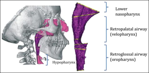
Anatomically, the airway can be divided into several segments along its path ( Fig 1 ). Evaluation of the upper airway has become an important diagnostic test in several subspecialties of dentistry, in part because of the controversial but potential impact of high-resistance airways contributing to abnormal growth of the nasomaxillary complex, resulting in an increased vertical facial dimension in young patients. Additionally, constricted airways are thought to play a potential role in the pathophysiology of obstructive sleep apnea. Traditionally, studies on the changes of the upper airway dimensions have consisted of analyzing the posttreatment effects with 2-dimensional (2D) cephalometric radiographs. Lateral and posteroanterior cephalometric radiographs have been used to compare the dimensional changes in the maxilla and the upper airway. However, the complexity of the 3-dimensional (3D) airway anatomy added to the superimposition of the bilateral structures, as well as magnification differences and difficulties in landmark identification, might have overlooked important anatomic features relevant to the airway analysis, thus questioning the accuracy of 2D representations. Major et al found that there was at best a moderate correlation (r = 0.68) between linear measurements of the upper airway in a 2D cephalometric film and the diagnosis of upper airway blockage, suggesting that 2D cephalograms should be used only as a screening tool for airway obstruction. The available 3D techniques, including magnetic resonance imaging and computed tomography (CT), might depict the true morphology of the airway, but their use is limited by high radiation, high cost, and restricted accessibility. Among the 3D imaging techniques, cone-beam CT (CBCT) has become an alternative technique to CT scanning for comprehensive head and neck evaluation because of its significantly lower overall effective radiation dose, greater spatial resolution than medical CT, high contrast between the hard and soft tissues, lower cost, and accessibility to dentists. Although CBCT is not a soft-tissue imaging modality, it is possible to determine the boundaries between soft tissues and air spaces, making it a potential diagnostic method to analyze airway dimensions.
The purpose of this study was to use 3D images from CBCT to prospectively evaluate the changes of the upper airway dimensions and the transverse width in orthodontic patients after RME therapy.
Material and methods
Fourteen children (5 boys, 9 girls) with a mean age of 12.9 years (range, 9.7-16 years) were recruited from the Department of Developmental Sciences/Orthodontics at the School of Dentistry, Marquette University, in Milwaukee, Wis. This research was approved by the university’s institutional review board. Informed consents from the patients and parents were obtained before the study. The inclusion criteria comprised young orthodontic patients (<16 years old) with unilateral or bilateral posterior crossbites, scheduled to receive RME as an initial part of their comprehensive orthodontic treatment. Exclusion criteria included craniofacial anomalies, previous orthodontic treatments, and systemic diseases. All patients were treated with a hyrax type of maxillary expander banded to the maxillary first premolars and first molars. The activation protocol consisted of 1 activation (90° turn) of the jackscrew per day for 28 consecutive days or until resolution of the posterior crossbite. Clinical observation of 2 to 3 mm of overexpansion marked the termination of expansion; the beginning of the retention phase consisted of tying off the jackscrew with a ligature wire and placing composite material over it. No additional orthodontic treatment was initiated in both jaws until after the retention phase started. The initial CBCT scan was taken 0 to 14 days before cementation of the maxillary expander, and the progress CBCT scan was taken 3 to 4 months after completion of active maxillary expansion to allow new bone to fill in the space at the midpalatal suture and the skeletal expansion to become stable.
All CBCT scans were taken by a certified radiologist (L.J.K.) at the radiology department at Marquette University, using a Scanora 3D device (Soredex, Tuusula, Finland) under an extended field of view mode (14.5 × 13.0 cm). The overall effective radiation dose was 125 μSv, with a 0.35-mm voxel size, a total scanning time of 20 seconds, and an effective radiation time of 4.5 seconds. The patients sat upright with the chin supported on an adjustable platform and the Frankfort horizontal plane parallel to the floor while the rotating source detector captured a volumetric image of the patient’s head. Immediately before scanning, all patients were instructed to keep their teeth in contact throughout the scanning process. These images were reconstructed and imported as digital imaging and communications in medicine (DICOM) data files into Dolphin imaging software (version 11.0; Dolphin Imaging & Management Solutions, Chatsworth, Calif) for observation and analysis.
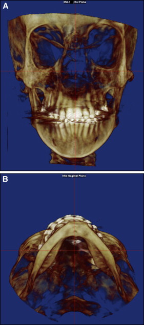
All CBCT images were oriented so that in the frontal view the skeletal midline (nasion to anterior nasal spine) was perpendicular to the floor, and in the axial view the midsagittal line (middle point between the maxillary incisors to posterior nasal spine) was perpendicular to the floor ( Fig 2 ). In patients with asymmetry, the orientation was made as close as possible to these guidelines. Once the image was properly oriented, the software was able to create a 2D simulated lateral cephalometric image at the midsagittal plane. From this view, the airway analysis tool was used to define the airway of interest. Because the nasal cavity contains multiple connecting air cavities, turbinates, and rarefactions, a clear segmentation was not possible, and it was excluded from our measurements.
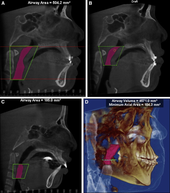
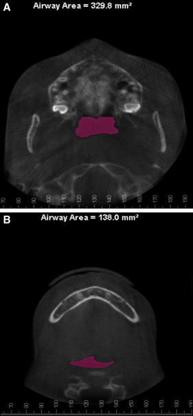
The upper airway ( Fig 3 , A ) was defined as the airway volume between the 2 planes as follows: the superior plane, arbitrarily called the “P plane,” was defined on the midsagittal image as the horizontal line connecting the posterior nasal spine to basion (because these anatomic points were closest to the upper airway and clearly shown on the sagittal plane of the CBCT image), and the inferior plane, arbitrarily called the “EP plane,” was defined as the horizontal line passing through the most superior point of the epiglottis. The upper airway was divided into 2 segments to further evaluate the specific effects of RME. The upper segment or retropalatal airway ( Fig 3 , B ) was limited superiorly by the P plane and inferiorly by a horizontal plane crossing the most posteroinferior point of the soft palate, arbitrarily called the “SP plane.” To increase the accuracy of the airway measurements, once the posterior nasal spine and basion points were selected in the midsagittal view, the P plane was reoriented so that it became parallel to the floor, and subsequent planes (SP and EP) were traced parallel to the P plane. The inferior segment or the retroglossal airway ( Fig 3 , C ) was limited superiorly by the SP plane and inferiorly by the EP plane. Once each airway had been demarcated, the Dolphin software allowed the selection of the airway by defining a threshold range of CT units that characterized all air spaces of the head and neck regions. We arbitrarily standardized the threshold range to 60 units (0-200 units were available) after observing consecutively that this unit provided the most comprehensive airway selection without adding or leaving out upper airway space, with the exception of 2 patients whose threshold range was decreased to 50 units. Because the air space has a lower CT value than the more dense surrounding soft tissue, it was possible to produce a clean segmentation of the airway. By using the sinus/airway analysis option, boundary position, seed point, and update volume option, airway volumes for the upper, retropalatal, retroglossal, and minimal cross-sectional airways ( Fig 3 , D ), and cross-sectional area for the P plane ( Fig 4 , A ), SP plane, and EP plane ( Fig 4 , B ) were obtained.
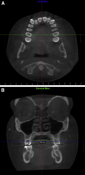
To evaluate the effect of the RME appliance on the transverse dimension, midlingual alveolar bone points were first located from the axial view for each of the maxillary first premolars and first molars, and their interbony widths were measured from the coronal view to enhance visibility and accuracy ( Fig 5 ). This step was performed with the digitize/measure option. All measurements were made by an author (Y.C.) who was trained and calibrated to identify 3D landmarks on the axial, sagittal, and coronal planes by the certified radiologist (L.J.K.).
Statistical analysis
Since the data were normally distributed, before and after RME dimensions (volumetric, sagittal, and cross-sectional) were compared by using the paired t test. Bonferroni adjustments were used to adjust for multiple comparisons. To improve accuracy, all measurements were repeated 3 times, 1 week apart, and the means were used for the comparisons. Intraexaminer reliability coefficients were calculated for 3 randomly selected parameters by using the Shrout-Fleiss reliability statistic. All analyses were based on a significance level of 0.05.
Results
The intraexaminer reliability coefficients for the randomly selected parameters were 0.995 for the sagittal area, 0.853 for the P plane cross-sectional area, and 0.982 for the first intermolar linear measurement. All measurements were considered to be reliable, since the reliability statistics were close to 1, which indicates perfect reliability. The CBCT scans after RME were taken an average of 105 days (range, 90-133 days) after the retention phase started. There was an average of 158 days (range, 119-211 days) between the first and second scans.
Table I shows the measurements of all variables in the 14 patients.
| Patient | Time | 6-6 (mm) | 4-4 (mm) | Retropalatal airway | Retroglossal airway | Total airway | |||||||
|---|---|---|---|---|---|---|---|---|---|---|---|---|---|
| P plane (mm 2 ) | SP plane (mm 2 ) | Volume (mm 3 ) | Sagittal area (mm 2 ) | MCA (mm 2 ) | EP plane (mm 2 ) | Volume (mm 3 ) | Sagittal area (mm 2 ) | Volume (mm 3 ) | Sagittal area (mm 2 ) | ||||
| 1 | T1 | 27.37 | 22.13 | 286.70 | 138.00 | 6006.10 | 247.63 | 138.37 | 128.37 | 5705.87 | 247.50 | 11711.97 | 495.13 |
| T2 | 33.10 | 26.67 | 449.000 | 286.33 | 13069.47 | 386.23 | 360.67 | 552.57 | 13988.80 | 434.67 | 27058.27 | 820.90 | |
| 2 | T1 | 36.17 | 27.40 | 119.27 | 153.93 | 5539.33 | 303.83 | 119.63 | 337.70 | 7405.97 | 316.87 | 12945.30 | 620.70 |
| T2 | 41.90 | 34.50 | 206.97 | 124.37 | 4717.17 | 263.80 | 104.30 | 293.13 | 5303.80 | 244.50 | 10020.97 | 508.30 | |
| 3 | T1 | 33.20 | 25.23 | 158.90 | 74.93 | 3531.13 | 179.33 | 71.50 | 65.80 | 2027.87 | 147.70 | 5559.00 | 327.03 |
| T2 | 36.60 | 29.00 | 313.47 | 78.47 | 4453.40 | 215.40 | 71.00 | 293.13 | 5567.57 | 292.90 | 10020.97 | 508.30 | |
| 4 | T1 | 30.63 | 25.23 | 281.40 | 100.10 | 9497.43 | 365.27 | 134.83 | 144.67 | 4372.63 | 252.53 | 13870.07 | 617.80 |
| T2 | 34.27 | 27.47 | 444.60 | 237.80 | 11089.90 | 367.80 | 293.33 | 367.77 | 9554.07 | 375.83 | 20643.97 | 743.63 | |
| 5 | T1 | 29.50 | 23.33 | 241.00 | 145.10 | 9461.07 | 402.57 | 224.70 | 316.60 | 6757.57 | 290.20 | 16218.63 | 692.77 |
| T2 | 34.97 | 28.97 | 273.90 | 142.97 | 10015.73 | 402.90 | 86.30 | 207.10 | 4023.80 | 206.43 | 14039.53 | 609.33 | |
| 6 | T1 | 30.83 | 22.60 | 161.80 | 98.63 | 3549.90 | 260.23 | 85.07 | 216.37 | 3526.70 | 205.27 | 7076.60 | 465.50 |
| T2 | 37.50 | 29.57 | 166.07 | 109.20 | 4181.33 | 258.07 | 101.93 | 239.00 | 4209.23 | 236.80 | 8390.57 | 494.87 | |
| 7 | T1 | 32.30 | 23.60 | 258.80 | 309.97 | 9911.33 | 425.40 | 262.67 | 261.70 | 5092.73 | 233.90 | 15004.07 | 659.30 |
| T2 | 35.40 | 26.47 | 367.27 | 96.40 | 5671.50 | 318.33 | 127.70 | 119.33 | 2775.27 | 192.07 | 8446.77 | 510.40 | |
| 8 | T1 | 31.32 | 21.83 | 77.23 | 77.20 | 3559.60 | 184.57 | 80.87 | 188.27 | 3526.47 | 190.63 | 7086.07 | 375.20 |
| T2 | 32.27 | 24.70 | 299.03 | 101.20 | 5100.23 | 213.17 | 103.47 | 259.20 | 4069.63 | 198.43 | 9169.87 | 411.60 | |
| 9 | T1 | 32.23 | 26.33 | 123.73 | 209.67 | 3983.60 | 184.00 | 113.93 | 230.13 | 8831.33 | 334.00 | 12814.93 | 518.00 |
| T2 | 38.93 | 32.50 | 142.33 | 201.50 | 3261.93 | 119.10 | 111.67 | 169.73 | 4816.10 | 186.53 | 8078.03 | 305.63 | |
| 10 | T1 | 30.77 | 22.50 | 422.23 | 260.63 | 12143.63 | 457.90 | 461.57 | 367.20 | 6707.60 | 274.93 | 18851.23 | 732.83 |
| T2 | 35.37 | 26.77 | 374.47 | 270.27 | 11003.70 | 445.37 | 303.47 | 196.43 | 4911.60 | 215.83 | 15915.30 | 661.20 | |
| 11 | T1 | 34.00 | 25.20 | 290.90 | 69.70 | 4869.73 | 216.17 | 102.93 | 103.97 | 3125.30 | 179.90 | 7995.03 | 396.07 |
| T2 | 39.40 | 29.57 | 325.70 | 36.27 | 4194.73 | 160.23 | 53.03 | 121.47 | 2747.80 | 129.73 | 6942.53 | 289.97 | |
| 12 | T1 | 27.47 | 18.53 | 364.00 | 219.17 | 8797.27 | 329.60 | 234.93 | 356.40 | 4246.33 | 223.30 | 13043.60 | 552.90 |
| T2 | 33.07 | 23.37 | 507.10 | 148.73 | 9984.70 | 314.13 | 195.17 | 246.93 | 3409.10 | 163.17 | 13393.80 | 477.30 | |
| 13 | T1 | 37.10 | 25.70 | 183.83 | 142.20 | 3872.03 | 239.83 | 137.07 | 204.03 | 3524.97 | 206.47 | 7397.00 | 446.30 |
| T2 | 40.57 | 30.50 | 321.70 | 256.87 | 8936.63 | 309.83 | 255.80 | 351.43 | 7470.87 | 209.20 | 16407.50 | 519.03 | |
| 14 | T1 | 33.83 | 26.43 | 233.03 | 130.40 | 3756.57 | 295.43 | 121.23 | 117.00 | 3383.10 | 286.43 | 7139.67 | 581.87 |
| T2 | 39.97 | 33.00 | 403.37 | 201.17 | 9615.63 | 497.97 | 179.80 | 196.93 | 2860.50 | 197.30 | 12476.13 | 695.27 | |
Stay updated, free dental videos. Join our Telegram channel
VIDEdental - Online dental courses


