CT and cone-beam CT technology provides clinicians with new methods to view patient anatomy exceeding conventional two-dimensional radiology. Interactive software applications allow for improved interpretation of the CT scan data. Proper use of this new technology must be based on a solid foundation of fundamental surgical and prosthodontic protocols. Advances in software and associated hardware have empowered clinicians with the necessary tools to harness the technology, while remaining true to conventional standards. The enhanced capability of innovative software applications that allow clinicians to interpret and maneuver through various three-dimensional images has far-reaching implications when interactive treatment planning software is combined with computer-aided design and manufacturing. Using all available virtual tools, true restoratively driven implant dentistry can be accomplished, ultimately benefiting patients.
Clinicians have been diagnosing, treatment planning, placing, and restoring modern dental implants using periapical and panoramic imaging films to assess bone anatomy for several decades. Two-dimensional film images have been found to have limitations because of inherent distortion factors, and the non-interactive nature of film itself provides little information regarding bone density, bone width, or spatial proximity of vital structures . Digital radiography permits some interaction to enhance diagnostic interpretation but ultimately remains two dimensional (2-D). It was not until CT scan technology became available for dental applications that the three-dimensional (3-D) properties of the jawbones and vital structures became apparent. The advent of 3-D reconstruction using CT or cone beam CT (CBCT) empowers clinicians with tools to simulate implant placement, bone grafts, or orthognathic surgical procedures in a true and accurate virtual environment . There are three basic views that a CT scan will provide: (1) panoramic, (2) axial, and (3) cross-sectional. The fourth view contains the 3-D reconstruction, and may differ in quality depending on the scanning machine and the software that is used to manage the CT data.
The original films that were the products of these scans provided clinicians with ample information, but no interactive ability, and therefore limited the diagnostic capabilities or the potential for collaboration with other technologies such as CAD/CAM (computer-aided design/computer-aided manufacturing). However, when innovative software applications permitted CT scan data to be viewed and manipulated on a desktop or laptop computer, a new world of anatomic realization was introduced. True, undistorted representations of the mandible or maxilla, combined with an array of tools for accurate treatment planning of realistic dental implants, abutments, and restorations are now possible. Manufacturer-specific CAD files have now been incorporated into libraries of data that can be manipulated within the framework of the virtual world of 3-D CT scan imaging. It is the combined enhanced capability of innovative software applications that allow clinicians to interpret and maneuver through various 3-D images that has far-reaching implications that will be explored in this article through the use of interactive treatment planning software in collaboration with computer-aided design and manufacturing.
Clinical applications
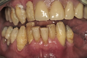
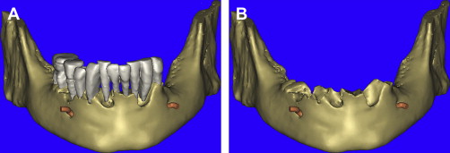
A 55-year-old male presented with severe and advanced periodontal disease in his remaining mandibular teeth ( Fig. 1 ). He had been informed about the hopeless prognosis of the mandibular teeth for many years, however his fear of dentistry prevented him from completing the recommended care. The seeding of bacteria as a consequence of the periodontal disease became a focus when other heart-related concerns were discovered. The patient was adamant in his desire to replace the teeth with a fixed prosthesis, as he did not think that he could tolerate anything removable. One of the reasons that he procrastinated about treatment was that he had been informed that the teeth were to be extracted, followed by a prolonged healing phase of approximately 4 months, implant placement, healing again followed by impressioning, and the prosthetic phase to complete treatment. The patient had not been made aware of any other alternative protocol for implant placement.
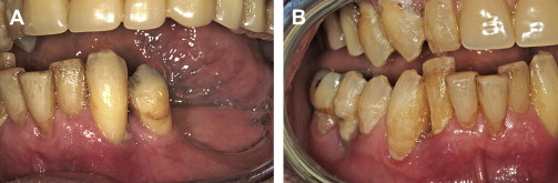
Intraoral examination revealed extreme mobility, with many teeth being held in place by the formation of a thick calculus bridge. There was swollen and edematous tissue, loss of attachment, and bleeding upon probing ( Fig. 2 A , B). To facilitate the diagnosis, the patient was informed about the benefits of 3-D imaging to help determine the extent of remaining bone that would be necessary to allow support for a fixed restoration. The patient was informed that without CT scan imaging, it would be impossible to understand the bony topography or assess the location of vital structures such as the inferior alveolar nerve. The patient was educated in the benefits of advanced planning to avoid potential complications and to determine what treatment alternatives were possible, taking the guesswork out of the process. The patient agreed, and a CBCT scan was taken using a NewTom 3G machine (AFP Imaging, Elmsford, NY.)
The scan was first evaluated using the machine’s native software (NNT, AFP Imaging), and was then exported into a form that would make the data accessible to interactive treatment planning software applications. The DICOM data (Digital Imaging and Communications in Medicine) was then imported into SIMPlant (Materialise Dental, Glen Burnie, MD) for detailed assessment of the anatomy and evaluation of potential implant receptor sites. The SIMPlant software converts the CBCT scan data into four basic undistorted interactive views for clinical evaluation: (1) reconstructed panoramic view, (2) axial view, (3) cross-sectional view, and (4) the 3-D view. Precise planning can be accomplished only when all of these views fully appreciated.
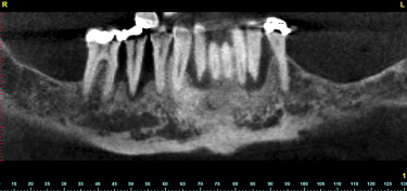
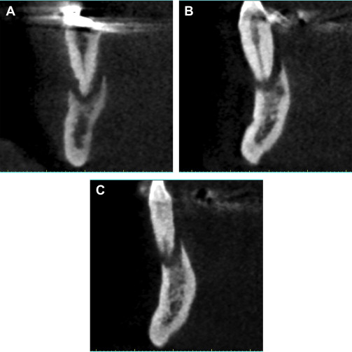
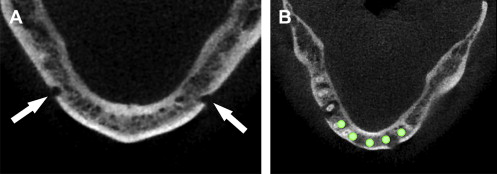
The reconstructed panoramic image revealed a 2-dimensional assessment of the mandible and the remaining teeth ( Fig. 3 ). The CBCT-generated panoramic view offers many benefits over conventional 2-D imaging with the interactivity of the software application. It is possible to scroll through the various panoramic images to help visualize the shape of the mandible and visualize the position of the teeth and path of the inferior alveolar nerve. It is also possible to change the gray-scale through a “windowing” of the CT scan data, which can also enhance the visualization of the anatomic structures. However, the ultimate power of 3-D imaging is the ability to use all of the available tools to diagnose and construct a treatment plan properly. After a viewing the panoramic reconstructions, the cross-sectional or coronal views are carefully evaluated. Moving around the arch, the destructive process of advanced periodontal disease was evaluated with greater appreciation of the facial and lingual bone loss, which could not be detected through the either conventional or CBCT-reconstructed panoramic images ( Fig. 4 A–C ).
Following the author’s standard protocol, the next step was to determine the location of the right and left mental foramina. This was accomplished by carefully assessing the continuity of the buccal cortical plate in the axial view. By scrolling inferiorly to superiorly through each axial slice, the break in the cortical buccal or facial bone indicated the exit path of the inferior alveolar or mental nerve. Depending on the scanning protocol and the position and symmetry of the patient, the right and left mental foramina may not be evident in the same axial slice. Thus, the right and left side may need to be assessed separately. The mental foramina can be clearly seen in Fig. 5 A . Once the bilateral foramina had been located, the path of the nerve was traced through the right and left posterior mandible. Planning implants in the anterior symphysis could then be accomplished, leaving an adequate zone of safety avoiding close proximity to the nerves ( Fig. 5 B).
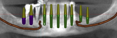
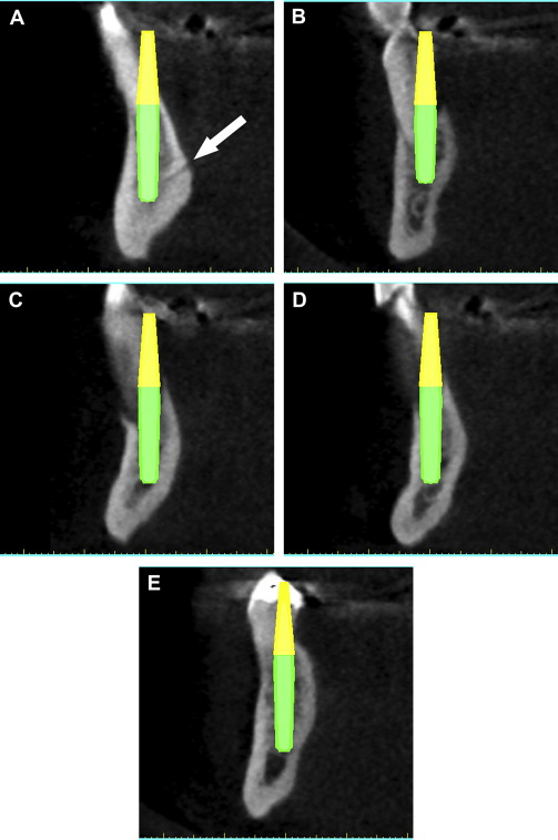
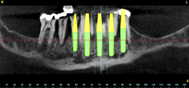
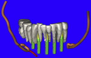
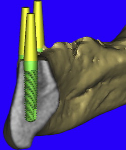
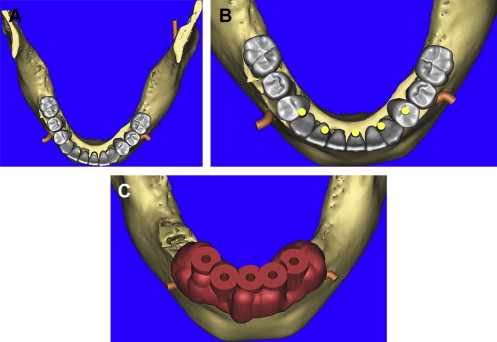
Using the panoramic, axial, and cross-sectional images, five potential receptor sites were found between the mental foramina, and two posterior receptor sites were located on each side ( Fig. 6 ). The removal of the remaining teeth in the anterior mandible would leave approximately 4 to 5 mm of residual alveolar crestal bone surrounding the postextraction sites. This bone was planned to be removed to gain adequate width of bone for immediate implant placement. Each placement was then individually confirmed in the cross-sectional images to ensure adequate bone volume surrounding the implant, and proper angulation, and position with regard the ultimate prosthetic reconstruction ( Fig. 7 A–E ). The yellow extensions projecting from the coronal aspect of each implant represent the potential abutment trajectories and are very useful in determining the relationship to the desired occlusion. The implants were specifically placed to gain adequate stabilization with the highest aspect of the remaining lingual cortical plate of bone, although some threads would be exposed on the facial. Additionally, visualization of other vessels (lingual) was noted to avoid potential complications (see Fig. 7 A). This process was not arbitrary, simplistic, or accomplished without careful attention to detail. The planning phase however, was not complete at this stage. The final “tweaking” and ultimate confirmation were completed after case presentation to the patient. After presenting several treatment plan options to patient, it was determined that five implants placed in the symphysis area would provide adequate support for a fixed hybrid restoration while meeting the patient’s needs ( Fig. 8 ).
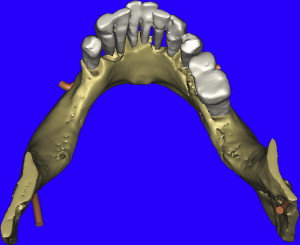
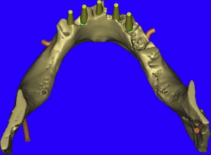
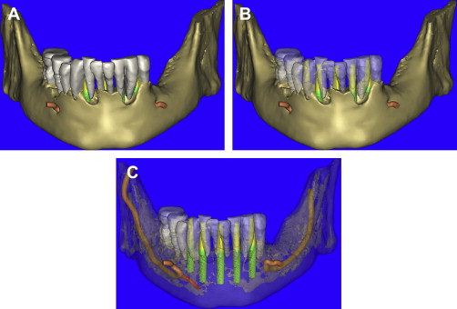
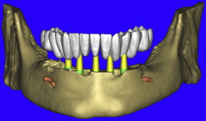
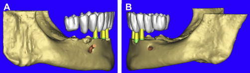
The opportunity to maximize the technological capabilities of CT/CBCT planning can only be realized when the 3-D dimensional reconstructed virtual models are used . Using advanced segmentation modalities found in SIMPlant Pro, or SIMPlant Master software application, the existing data were converted into high-resolution models that can be rotated and viewed in any position on the computer screen ( Fig. 9 A ). The bone and the teeth were separated by using 3-D masking tools providing a picture of the extraction sites that could not be visualized by any other means (see Fig. 9 B). The ability to appreciate the bone topography in this manner cannot be underestimated. The lingual view of the existing teeth and mandible can be seen in Fig. 10 . Using sophisticated masking tools allowed the remaining natural teeth to be “removed” from the 3-D model, to help visualize the positioning of the implants within the bony housing of the extraction sites, and enhance the capability to accurately assess proximity to the mental foramina ( Fig. 11 ). Without masking, it would be difficult to properly assimilate all of the elements to finalize the plan ( Fig. 12 A ). However, other tools can also aid in this process. The use of transparency enabled the implant abutment projections to be seen through the translucent teeth in Fig. 12 B. Further application of the transparency effect can be very useful in appraising the parallelism of the implants and proximity to the path of the inferior alveolar nerve (see Fig. 12 C). When the 3-D mandibular bone was removed entirely, the clinical crowns and root morphology were readily apparent ( Fig. 13 ). An anterior loop of the right inferior alveolar nerve was noted and appreciated in finalizing the spatial position of the implants (see arrow in Fig. 13 ).
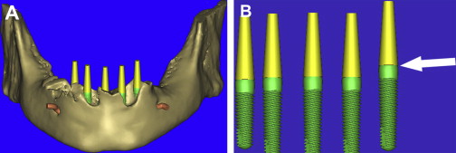
As previously discussed, the residual alveolar process was to be reduced after extraction of the remaining teeth. Using 3-D modeling enables a precise consideration of the bony site for proper reduction based on the needs of the reconstruction ( Fig. 14 A ). Before virtually reducing the bone, the vertical positioning of the implants can be appreciated by visualizing the actual representation of realistic implants. The interactive software application contains a library of manufacturer-specific implants by type, diameter, and length. Many implant manufacturers have supplied CAD files for use in the software application, greatly enhancing the planning capability. For this case, five Tapered Screw-Vent implants (Zimmer Dental, Carlsbad, CA) were used. The actual realistic CAD implants were then used for final visualization revealing the shape, thread pattern, apical configuration, and internal aspect of the prosthetic connection. It is the author’s contention that placing all implants parallel and at the same vertical position (if possible), aids the prosthetic and laboratory phase of a screw-retained prosthesis. By removing the bone from the 3-D view, it was found that not all of the implants were placed at the same vertical dimension (see Fig. 14 B). Parallel placement was easily accomplished by use of the “paralleling” tool in SIMPlant. Vertical “tweaking” was accomplished with the “translation” tool, which can move the implant in very precise, small increments. Final confirmation was achieved by slicing through the 3-D view to reveal the bone, the implant, and the yellow abutment projection ( Fig. 15 ).
When there is an edentulous mandible or maxilla, a radiopaque barium sulfate template of a diagnostic wax-up or duplicate denture can be made in advance to be worn during the CT scan process. This scanning or “scannographic” template can then help to determine the ideal position of the teeth in relation to the underlying bone . When existing teeth are present, as in this case presentation, this becomes more difficult. Therefore, a new tool (Virtual Teeth), originally envisioned by the author in early 1994, was recently introduced as a continually evolving application within SIMPlant to aid in assessing the restorative needs for any edentulous site, whether it be a single tooth or full arch. It is the author’s contention that these interactive planning tools will play a significant future role for linking CT scan planning data to CAD/CAM applications .
Using the virtual tooth tool, a “virtual occlusion” was configured over the existing dentition allowing for a CAD representation of the desired tooth position ( Fig. 16 ). The 3-D mandibular bone was also virtually “reduced” by 4 to 5 mm, and the vertical placement of the teeth was easily appreciated in all views ( Fig. 17 A , B). The use of CAD virtual teeth can help in assessing the final prosthesis design by helping to understand crown-to-root ratio, and the need for pink acrylic or porcelain flanges for lip support or cosmetics. The occlusal view of the 3-D mandible and virtual occlusion demonstrate this valuable prosthetic tool ( Fig. 18 A ). The close-up view in Fig. 18 B reveals the yellow abutment projections and their relationship with the occlusal scheme. By using these 3-D tools, the surgical and prosthetic team can easily assess the final proposed result before ever touching the scalpel to the patient, minimizing potential problems resulting from malpositioned implants (see Fig. 18 C). In this manner, using all of the tools available, true restoratively driven implant dentistry can be accomplished. When the plan has been finalized, the data are sent via e-mail for fabrication of a bone-borne surgical template that will serve as the definitive guide for the placement of the implants (Materialise Dental, Lueven, Belgium).
Surgical intervention
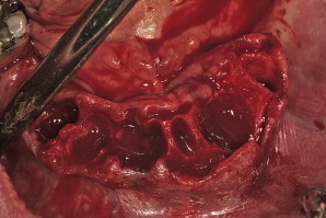
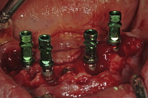
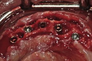
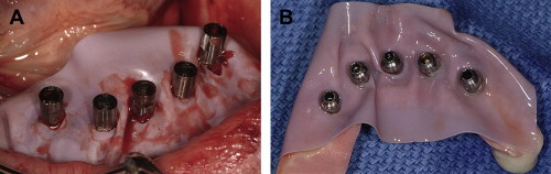
Surgical templates have been fabricated in several forms: (1) the original bone-borne template, (2) the tooth-borne template, and, more recently, (3) a soft tissue–borne template. As this particular case presentation involved tooth extraction, bone reduction, and implant placement, it was elected to use a bone-borne template. There is an important caveat with regard to tooth extractions and alveolectomy when working with bone-borne templates: do not remove the bone until all osteotomies have been prepared. If the bone is modified before use of the template, it will no longer fit accurately to the underlying bone . Tooth extractions should always be done atraumatically, taking care not to remove bone if possible. The bony foundation should remain intact to allow for stability and fit of the bone-borne template. Therefore, bone reduction is a step that follows the osteotomy preparation, not before. A technique that was not demonstrated for this case involves using a special “bone-reduction template” that can be fabricated through stereolithography to achieve a high level of accuracy when planning to place implants simultaneous to substantial vertical bone reduction in the anterior symphysis . The extractions were performed and the soft granulation or cystic tissue was carefully removed ( Fig. 19 ). Using the bone-borne templates, five osteotomies were drilled into the mandibular bone as per the CT scan. Once the osteotomies were prepared, the bone was leveled to achieve the anticipated dimension. Five tapered screw-vent implants were then successfully placed (Zimmer Dental, Carlsbad, California). Four of the implants with their attached fixture mounts demonstrate parallelism, with the fifth or middle implant at the desired vertical height of bone level to the lingual cortical plate ( Fig. 20 ). Proper implant spacing, and the residual, remaining bone defects are evident in Fig. 21 . Autogenous bone was collected from each site and mixed with mineralized bone to fill the defects to support the soft tissue. Collagen strips (Collacote, Zimmer Dental) were soaked in sterile saline solution and placed over the entire surgical site. Five titanium, direct-to-the implant, screw-receiving cylinders (Titan Implants, Bergenfield, New Jersey) were attached to each implant, and the soft tissue approximated and sutured using 4-0 vicryl sutures.
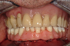
Once the site had been sutured, a rectangular piece of rubber dam material with pre-punched holes was placed over each cylinder and adapted to the underlying soft tissue. A prefabricated prosthesis was placed over the cylinders, and cold-cure acrylic injected into horizontal holes to fixate the cylinders ( Fig. 22 A ). The prosthesis was then removed to add and/or trim the acrylic (see Fig. 22 B). Once polished, the prosthesis was screw-retained to the implants, and the bite adjusted ( Figs. 23 and 24 ). The transitional prosthesis was fabricated as a duplicate of the original position of the patient’s natural dentition. Postoperative instructions were given to the patient, with specific instructions as to use of a soft diet on the immediate load restoration. The patient returned after 2 weeks with normal healing, and report of little swelling or pain. All of the sutures were then removed, and the patient was followed for 8 weeks to monitor healing.
Stay updated, free dental videos. Join our Telegram channel
VIDEdental - Online dental courses


