CHAPTER 2 Miniscrews and biomechanics in orthodontics
Introduction
In the past few decades, orthodontic techniques – from the Andrews Straight-Wire™ Appliance1 to the MBT™ Versatile+ appliance – have greatly evolved in the aspects of tipping, torque, rotation and bracket design. This evolution has been based on the search for a technique that would enable ease of appliance set up with a bracket prescription that would provide good torque, tip, rotation and anchorage control, during all the stages of orthodontic treatment.
Miniscrew anchorage also helps deliver more predictable orthodontic treatment,2 allowing optimal use of sliding mechanics with low force levels and more favorable biological responses in a variety of situations. For example: when distalizing molars in Class II treatment and Class III treatment; in retraction of the anterior teeth, in extraction as well as in non-extraction cases; for posterior vertical control in patients with high mandibular angles; and for anterior vertical control in overbite cases.
SmartClip™ Self-Ligating Appliance and orthodontic miniscrews
The use of miniscrews in conjunction with the SmartClip™ Self-Ligating Appliance3 favors optimal application of sliding mechanics during tooth movement. The SmartClip™ Self-Ligating Appliance System with its reduced friction allows the application of low force levels compared with conventional bracket systems. It also has less anchorage requirements during alignment, leveling and space closure stages of treatment.
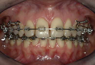
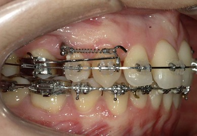
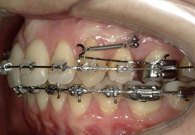
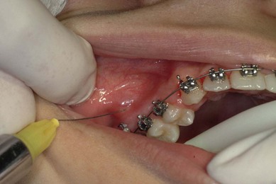
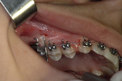
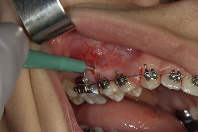
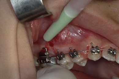
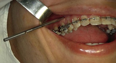
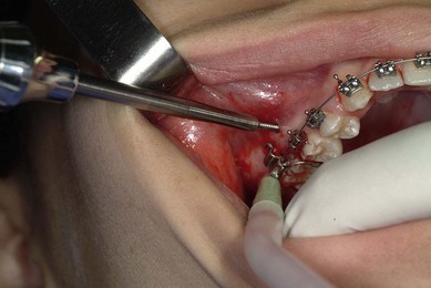
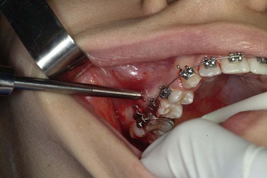
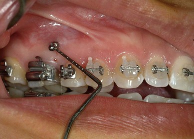
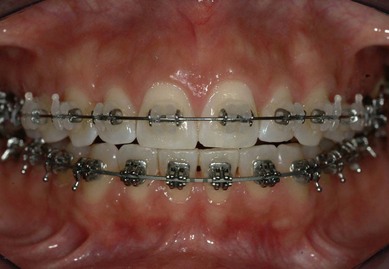
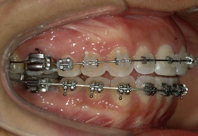
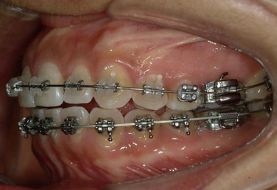
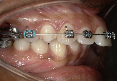
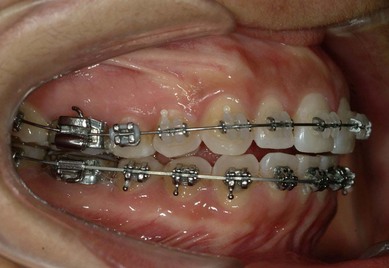
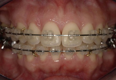
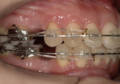
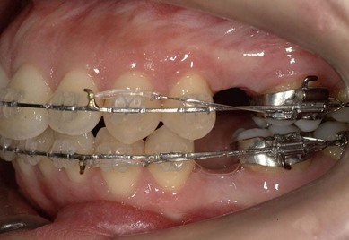
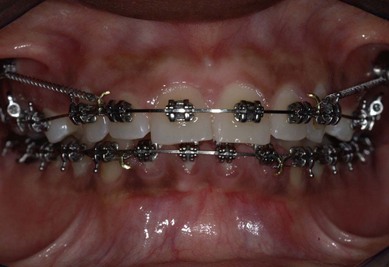
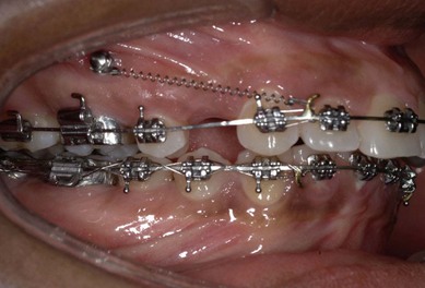
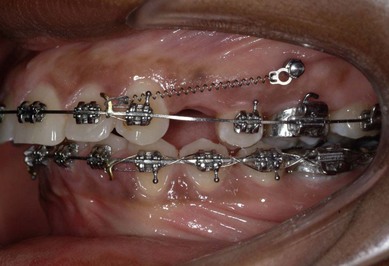
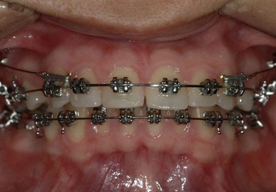
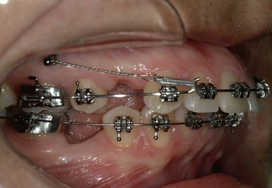
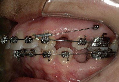
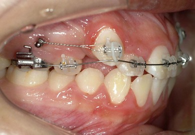
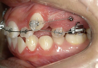
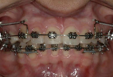
Classically, with the use of conventional appliance systems, friction is caused by the use of elastic and metal ligatures to keep the archwire engaged in the bracket slot. In the absence of these modalities, there is a decrease in the force levels required for the treatment, resulting in less undesired tooth movement (Figs 2.1, 2.2 & 2.3).
Miniscrews: type, shape and size
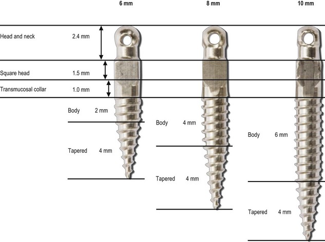
There are several types of orthodontic miniscrew.4 The Unitek™ Temporary Anchorage Device (TAD) System is a self-tapping system that does not require pre-drilling of the cortical plate or the alveolar bone. The Unitek™ TAD features a 4 mm tapered body shape and, because it is a self-tapping system, its insertion is easier as there is no need for heavy force application.
The other characteristics of the Unitek TAD System are (for all three sizes):
Surgical protocol for the insertion of miniscrews
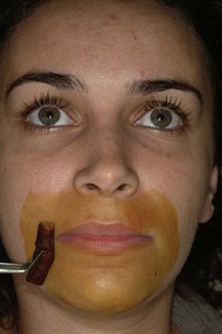
The surgical protocol5 has three important steps that should be carefully planned. The stability of the miniscrew device in either the maxilla or the mandible depends on both proper positioning of the miniscrew and on the clinician carefully following the steps of insertion, which are as follows:

Planning the placement of the orthodontic appliances to allow insertion of miniscrews
Regardless of the presenting malocclusion and the biomechanics to be applied, every orthodontic case requires pretreatment planning as to placement of the appliance. This is also the case when miniscrews are inserted as the anchorage device.6 Planning the appliance set-up allows the use of well-established biomechanics with more efficiency, avoiding undesired tooth movement and decreasing treatment time. Thus the clinician should place an orthodontic appliance with due consideration of the biomechanics to be applied and keeping in mind the following four points:
Miniscrews as anchorage system in premolar extraction cases
In conventional treatment, in the beginning of the alignment phase, when the canines are individually retracted, and in the space closure stage, when closing the remaining spaces, .019/.025 rectangular stainless steel archwires with prewelded hooks to the mesial of the canines should be used (Figs 2.26, 2.27 & 2.28). The line of action of the force applied with conventional sliding mechanics in extraction cases lies close to the bracket slot and parallel to the orthodontic archwire. To correct open bites and deep bites, bends are added to the archwire and, occasionally, an anchorage system is used.
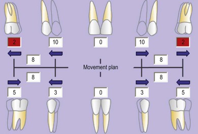
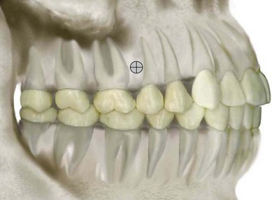
In orthodontics, use of the dental visual treatment objective (dental VTO)7 analysis during treatment planning is particularly helpful in establishing the precise anchorage requirements for treatment in Class II cases. The dental VTO allows the clinician to provide more efficient and accurate treatment as it enables the simulation of the proposed anterior and the posterior tooth movements (Fig. 2.29) and cephalometric prediction of the final positioning of the incisors and the occlusion of the molars and premolars.
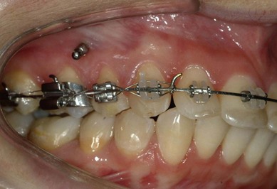
Temporary skeletal anchorage devices, e.g. miniscrews, offer the orthodontist a new approach to orthodontic biomechanics. In premolar extraction cases, miniscrews are generally inserted mesial to the first molars to aid in the application of direct space-closing forces. The vertical positioning varies depending on the vertical growth pattern of the patient. In cases with severe overbite, the position of the miniscrew should be above the center of resistance of the upper molars, enabling intrusion of the upper anterior teeth via the vertical component of force thus established (Figs 2.30, 2.31 & 2.32). In cases of moderate overbite, the vertical positioning of the miniscrew should be in the keratinized gingiva, close to the center of resistance of the teeth (Figs 2.33, 2.34 & 2.35).
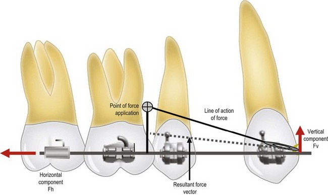
The choice of the ideal insertion point8 for the miniscrew in the maxilla is very important for the stability of the miniscrew and the biomechanics. In premolar extraction cases, the ideal vertical position of the miniscrew is close to the center of resistance of the teeth, approximately 8 mm above the orthodontic archwire. In this way, when the point of force application is at a distance from the orthodontic archwire, vertical force vectors are generated that help in reduction of deep overbite (Fig. 2.36).
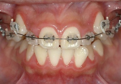
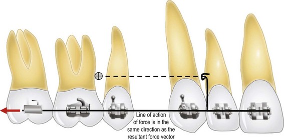
In cases with reduced or normal overbite, the orthodontic treatment should be initiated with individual retraction of the canines, and application of horizontal forces without any vertical force components, which are not helpful in these patients (Figs 2.37, 2.38 & 2.39). After the initial correction of the overbite, the line of force application should be changed by using a larger hook, welded to the mesial of the canines. This hook should be made with .019/.025 rectangular stainless steel archwire, and should be level with the miniscrew. The line of force application should be parallel to the orthodontic archwire (Figs 2.40, 2.41 & 2.42). When the line of force action is applied parallel to the orthodontic archwire, the direction of tooth movement will be parallel to the archwire (Fig. 2.43).
Class II treatment with molar distalization using miniscrews
Molar distalization using miniscrews
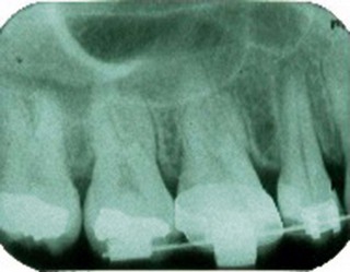
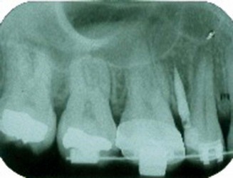
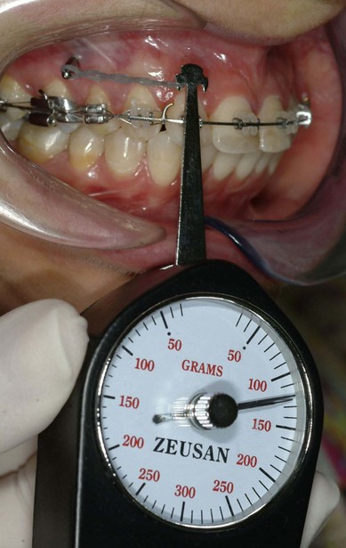
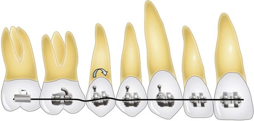
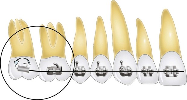
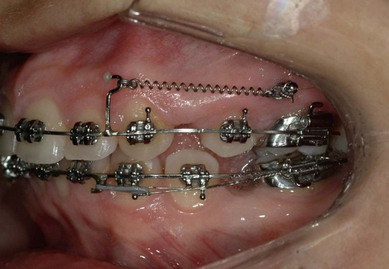
One of the main difficulties in orthodontics has been the treatment of unilateral Class II malocclusions, especially in adult patients, as existing appliances do not allow unproblematic application of sectional biomechanics. However, now with miniscrews it is possible to integrate anchorage devices with the fixed orthodontic appliances. Thus, during molar distalization,9 force application can be more predictable. Patient comfort and hygiene are also greatly improved due to the reduction in attachments used to apply the biomechanics. In Class II cases that require molar distalization, the site of insertion of the miniscrew should be occlusogingival, mesial to the first molars within the keratinized gingiva, concurring with the WALA ridge established by Andrews10 (Figs 2.44 & 2.45). The interradicular space between the roots of the first molar and the second premolar, as well as the height of the alveolar bone crest, should be verified with periapical radiographs prior to the insertion. If there is insufficient space, it should be opened up by bonding the second premolar bracket in a counter-angulated position to move the roots mesially (see Fig. 2.24). The miniscrew recommended for distalizing molars in Class II cases is the 8 mm length screw. The force applied should be 250 g.
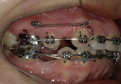
There are two ways of distalizing the molars. The first is to use the fixed appliance without an auxiliary tube on the upper molars. In this case, a jig should be made with stiff .022 round stainless steel archwire, applying the force to the mesial of the molars (Figs 2.46, 2.47 & 2.48). The resulting force vectors do not allow full control over molar tipping, e.g. the molar may show more distal tipping. The angulation of the molar root is controlled by the main archwire. In this stage of treatment, the patient should have a .019/.025 rectangular archwire, which has been reduced posteriorly. The second option is to distalize the molars using an auxiliary tube which has been positioned on the gingival aspect of the band or the bonded tube. Figures 2.49 & 2.50 show an adult patient in whom right upper molar distalization was planned with an auxiliary tube. A force of approximately 150 g should be applied immediately after the appliance is set up for 20 days and subsequently increased to 250 g.
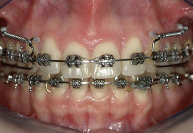
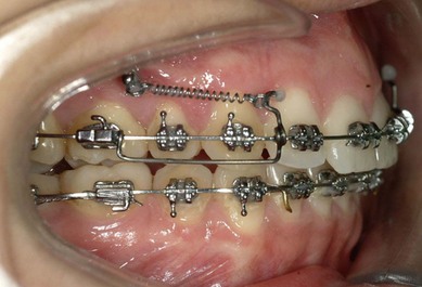
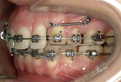
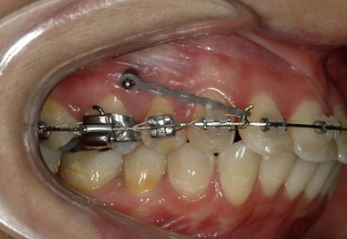
Fig. 2.50 Figs 2.49 & 2.50 Upper first molar band with gingival tube for distalization. Figure 2.18 shows the force of approximately 150 g being applied for the first 20 days.
The jig is built with .019/.025 rectangular stainless steel archwire, going from the me/>
Stay updated, free dental videos. Join our Telegram channel
VIDEdental - Online dental courses


