Introduction
In this study, we aimed to assess the ability of a new viscoelastic finite element method model to accurately simulate rapid palatal expansion with a miniscrew-supported hybrid hyrax appliance.
Methods
A female patient received 3-dimensional craniofacial imaging with computed tomography at 2 times: before expansion and immediately after expansion, with the latter serving as a reference model for the analysis. A novel approach was applied to the finite element method model to improve simulation of the viscoelastic properties of osseous tissue.
Results
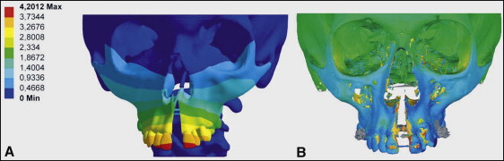
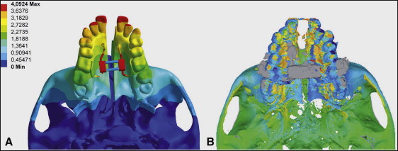
The resulting finite element method model was a suitable approximation of the clinical situation and adequately simulated the forced expansion of the midpalatal suture. Specifically, it demonstrated that the hybrid hyrax appliance delivered a force via the 2 mini-implants at the center of resistance of the nasomaxillary complex.
Conclusions
The newly developed model provided a suitable simulation of the clinical effects of the hybrid hyrax appliance, which proved to be a suitable device for rapid palatal expansion.
Initial studies with finite element method (FEM) analysis in the dental field were conducted in the 1970s. At that time, the limited technology only allowed the use of simple models that were tailored to a specific problem. However, a decade later, Tanne et al published an article and used a more complex model to simulate the effects of maxillary protraction on the midface.
A different orthopedic measure that also affects the midface, among other areas, is rapid palatal expansion, which was initially described by Angle. Further developments by Haas and Biederman established it as a well-accepted technique for the treatment of maxillary transverse deficiencies. With favorable anatomic circumstances, the traditional tooth-borne rapid palatal expander has been shown to effectively increase the maxillary transverse dimension, albeit causing considerable side effects in terms of buccal tipping of the anchorage teeth and associated fenestrations of the buccal cortical plate, root resorption, and gingival recessions.
Rapid maxillary expansion is a rather complex treatment that was shown to have effects on the maxilla in all 3 dimensions. Traditionally, it is carried out by using a tooth-borne appliance with a center jackscrew that translates 2 equal and opposite, but collinear, forces onto the maxillary halves, attempting to spread them apart. Early experiments on dry skulls suggested that, in the coronal plane, this results in lateral rotations of both maxillary halves, with the center of resistance slightly above the piriform aperture at the frontomaxillary suture. In the axial plane, the center of rotation appears to lie in the posterior maxillary suture at the level of the third molars. Lastly, sufficient evidence suggests a mild downward movement of the maxillary complex when rapid palatal expansion is applied.
To better understand the treatment effects of rapid palatal expansion, this common treatment method has been the focus of many FEM studies in recent years. The goal of our study was to test the ability of a newly developed viscoelastic FEM model to accurately simulate the treatment effects of the partially bone-borne hybrid hyrax appliance.
Material and methods
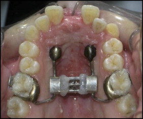
This study was conducted by using existing image data of a 16-year-old female orthodontic patient who was treated for maxillary transverse deficiency with a hybrid hyrax appliance (SnapLock Expander; Forestadent, Pforzheim, Germany); it is a modified expansion appliance that is attached to the maxillary first molars and anteriorly supported by 2 orthodontic mini-implants ( Fig 1 ). This design was proposed by Wilmes et al, Wilmes and Drescher, and Wilmes et al as the “hybrid hyrax.” The 2 mini-implants (Ortho Easy; Forestadent) were 8 mm in length and 1.8 mm in diameter, and were inserted in the anterior palate, 2 mm to the paramedian aspect of the midpalatal suture. This implant location was chosen because previous studies suggested that the center of resistance of the nasomaxillary complex is located in the premolar region. Coincidentally, this also appears to be the most ideal location for palatal miniscrew insertion from an anatomic perspective.
For the construction of the 3-dimensional model, the patient’s head was imaged by using low-dose dental computed tomography (Brilliance 16; Siemens, Munich, Germany), with a horizontal slice thickness of 0.4 mm and a vertical slice thickness of 0.8 mm, at 2 times: T1, immediately before expansion; and T2, immediately after expansion.
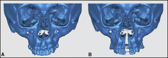
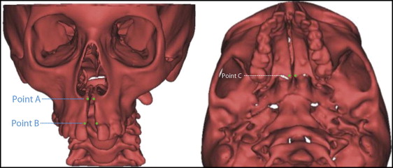
The image data were saved as a digital imaging and communications in medicine (DICOM) file and later converted to a stereolithography file by using OsiriX software (Pixmeo, Geneva, Switzerland). The resulting 3-dimensional images were so precise that individual sutures could be readily identified, and the skeletal treatment effect became visually apparent in terms of sutural widening ( Fig 2 ). The 3-dimensional stereolithographic images at T1 and T2 were used for superimposition at the anterior cranial base to assess both dental and skeletal treatment effects. The changes were highlighted by using Qualify software (Geomagic, Stuttgart, Germany) ( Figs 3 and 4 ). The T2 image serves as a reference for the simulation. By superimposing the simulated model and the actual postexpansion image, the accuracy of the simulation could be assessed. Only a high level of congruency between both would indicate an accurate simulation. To allow accurate metric comparison of the actual and the simulated treatment results, we defined different points in all 3 planes of space ( Fig 5 ).
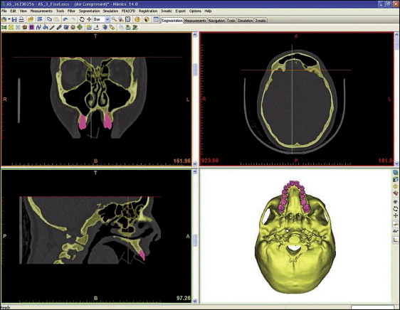
The first step in creating the FEM model is to generate a 3-dimensional geometric model of the skull and the dentition. This was accomplished by segmenting the computed tomography data and then converting it into stereolithographic form by using Mimics software (version 14; Materialise, Leuven, Belgium). The stereolithographic format shows a surface view of the segmented structures and serves as scaffolding for the FEM mesh. The segmenting is illustrated in Figure 6 .