Anchorage is resistance against undesired tooth movement. In modern orthodontics, anchorage loss can be a significant complication during treatment. Therefore, anchorage control is an important issue that needs to be addressed right from the leveling stage.
Uncontrolled tipping is the easiest tooth movement to accomplish with orthodontic appliances, whereas root movement is the most difficult and complicated. The concept of anchorage preparation has been used for several years in the Tweed technique to reinforce anchorage through anchorage bends before anterior retraction. In those cases wherein anchorage bends are not sufficient, the anchorage teeth must be actively reinforced with auxiliaries. This anchorage reinforcement can be achieved in several ways.
Intraoral Methods
Increasing the number of teeth
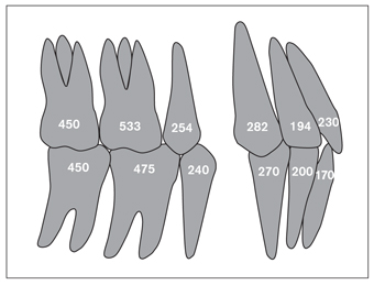
The simplest and most practical way of reinforcing anchorage is to increase the number of teeth by binding them together with a figure-eight ligature. The number of roots and the root surface areas affect the anchorage capacity of a tooth. Theoretically, a three-rooted tooth has more anchorage value than a single-rooted tooth1 (Fig 5-1). The type of movement (ie, tipping or root movement), however, defines the real capacity of the anchorage of a tooth. Under the effect of root movement, the anchorage value of a single-rooted tooth (ie, maxillary canine) can overcome that of a maxillary molar (ie, the rowboat effect; see chapter 3). Clinically, as far as anchorage is concerned, one should not fully rely on the number of teeth and roots, but on the force system acting on them.
The Nance appliance
The Nance appliance is an auxiliary arch used in conjunction with fixed appliances in moderate anchorage cases. The Nance appliance has an acrylic button placed anteriorly at the deepest point of the palate. The two ends of the arch are either soldered to the palatal aspects of the maxillary molar bands or are inserted into the palatal tubes. The shape and depth of the palate plays an important role in the retention of the Nance appliance. If the palate is shallow anteriorly, the acrylic button may slide on the palatal mucosa, so narrower and deeper palates are more suitable for this type of retention. The acrylic button should be prepared wide enough to cover the anterior part of the palate. A small button will not provide enough anchorage support and may puncture the palatal mucosa.
Even though the mucosa in contact with the acrylic button is resistant and covered with a thick keratin layer, it might not resist high, continuous forces. It has been shown that chronic inflammation has developed on the mucosa under the acrylic button due to heat and lack of hygiene.2 The force, therefore, should be optimal, and the Nance appliance should be removed as soon as it is no longer needed for anchorage.
Uprighting springs
Uprighting springs are used to reinforce the resistance of the first premolars, which serve as anchorage in molar distalization with a combination of superelastic nickel-titanium (NiTi) coil springs and the Nance appliance. When these springs are activated after being placed in the vertical slots of the premolar brackets, they apply mesial root torque, creating resistance against mesially directed forces by the coil springs (Fig 5-2).
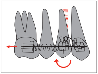
Fig 5-2 Uprighting springs increase the resistance of premolars against mesially directed forces during molar distalization, and a clockwise moment by the uprighting spring creates distal crown movement of the first premolar.
Sliding jig
A sliding jig, used in combination with intramaxillary and intermaxillary elastics, can be accepted as an anchorage reinforcement auxiliary. Consisting of a 0.7-mm wire with a hook, the sliding jig slides along the main archwire and transmits the Class II elastic force directly to the molar. The mechanics of this appliance are explained in detail in chapter 8.
Cortical bone anchorage
The principle of the cortical bone method is based on the biologic differences between cortical and trabecular bone. Teeth move more easily in trabecular bone than in cortical bone. If the roots of the anchorage teeth are in cortical bone, their resistance to movement is increased. Ricketts3 has suggested putting active lingual root torque on mandibular canines to place them in trabecular bone before distalization to make movement smoother.
Active buccal root torque can be placed in molars to increase their anchorage against mesially directed forces. A transpalatal arch can be used for this purpose. Both ends of the arch should be inserted at equal angles into the molar tubes to obtain equal and opposite moments and avoid vertical balancing forces (Fig 5-3).
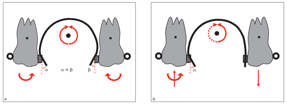
Fig 5-3 Cortical bone anchorage prevents the molars from moving mesially. A transpalatal arch moves the roots by reciprocal anchorage. (a) Obtaining equal and opposite moments is important to avoid vertical balancing forces. (b) Unequal moments may cause an imbalance in the occlusion.
Transpalatal arch
Transpalatal arches reinforce posterior anchorage by incorporating maxillary right and left molars (see chapter 8). Root4 stated that in a case involving a transpalatal arch, the anchorage value needed to correct a malocclusion in the mandible decreases by 1 mm in approximately 1 year. Soysal5 claims that the transpalatal arch can be an alternative to headgear even in cases needing strong anchorage. However, the transpalatal arch cannot resist anteroposterior forces as effectively as headgear, but it can be used in moderate anchorage cases.
Lip bumper
The lip bumper is used to reinforce anchorage of mandibular molars by taking support from mentalis muscle activity. In fact, it is a myofunctional appliance used to eliminate the compressing effect of the mentalis muscle forces on the mandibular dental arch, especially in the transitional dentition. Retraction of the mentalis and buccinator muscles causes an expansion of the mandibular arch at the premolar and molar area and protrusion of the incisors by the tongue forces. Expansion of the molars can also be obtained by widening the arms of the arch. Because the force is applied directly onto the mandibular molars, it helps reinforce molar anchorage and even helps upright them (Fig 5-4). As the anteroposterior and transverse sizes of the mandibular arch are increased, mild crowding in the incisor area can be corrected spontaneously.6,7 Size and stability of arch form obtained with the lip bumper can be maintained with a lingual arch until eruption of the permanent dentition.
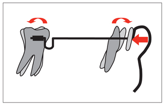
Fig 5-4 The lip bumper reinforces anchorage of the mandibular molars using mentalis muscle force.
Extraoral Appliances
Extraoral appliances have been the strongest and most reliable anchorage reinforcement method for several years. Approximately 300 to 350 g is sufficient force to prevent the posterior teeth from moving mesially.8 Patient cooperation is key to the success of headgear treatment, and headgear timers can be helpful in that area.9–11
Extraoral appliances can be categorized as those that apply forces from anterior to posterior in Class II cases and those that apply forces from posterior to anterior in Class III cases. This chapter focuses on Class II types that apply force by means of a facebow, which is used in most cases.
The objectives of using extraoral appliances are listed under five headings:
1. Anchorage reinforcement
2. Creating an orthopedic effect on the jaws
3. Providing vertical control of the face
4. Changing the occlusal plane inclination
5. Tooth movement
Anteroposterior force application
In skeletal Class II cases, the main purpose of extraoral force is to control or redirect forward and downward growth of the maxilla. Besides its skeletal effects, extraoral force also has dental effects such as distalizing maxillary molars to gain space on the dental arch and reinforce the anchorage. Extraoral appliances can be used either on their own or combined with fixed appliances, usually on the maxillary first molars.12–14
Extraoral appliances are classified by different authors according to their direction of force, length, or angulation of their outer arms. Facebows of various dimensions are manufactured according to dental arch sizes.
These are used with short, medium, or long outer arms, depending on the needs of each patient. The aim here is not to prescribe, but rather to state the general mechanical principles of extraoral forces, helping orthodontists select suitable appliances for their particular patients.
The main criterion in selecting extraoral appliances is the vertical growth pattern of the face. In low-angle cases, cervical-pull forces (cervical headgear) should be used because the direction of pull is backward and downward. The vertical component of this force vector pulls the molars down, causing clockwise rotation of the mandible. This leads to bite opening,8 which is desirable in low-angle patients. In patients with high condylar growth potential, the effect of cervical headgear can be compensated for by condylar growth.15
In high-angle cases, a high-pull or vertical-pull extraoral force, which applies an upward pull, must be used. The pulling direction of these appliances is backward and upward. This force direction provides vertical control of the posterior segment by preventing eruption of the molars and sometimes intruding them. In high-angle cases, this prevents clockwise rotation of the mandible and even promotes counterclockwise rotation. For this to occur, however, the patient must have sufficient condylar growth potential.
Analysis in the sagittal plane
Extraoral forces are applied between either the neck or different parts of the head and the outer arms of the facebow and transferred to the molars through the inner arms. The relationship between the line of action of the force and the center of resistance of the molars determines the movements of these teeth.
Cervical headgear
The application of cervical headgear on the molar tubes is shown in Fig 5-5. The direction of force is backward and downward; therefore, the force has horizontal and vertical components. If translation of the molars is indicated, the line of action of the force should pass through the center of resistance of the molars (Fig 5-5a). If the line of action passes below the center of resistance, the molar undergoes clockwise rotation as well as translation (Fig 5-5b). This will cause the crown to move distally while the roots move mesially. If the line of action of the force passes above the center of resistance (Fig 5-5c), the molar rotates counterclockwise as well as translates.
High-pull headgear
High-pull force passing through the center of resistance causes translation with intrusion (Fig 5-6a), while force passing below the center of resistance causes clockwise rotation (Fig 5-6b), and force passing above the center of resistance causes counterclockwise rotation of the molars (Fig 5-6c).
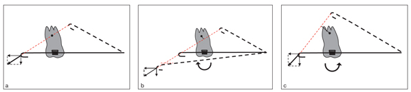
Fig 5-5 The direction of force in cervical headgear is backward and downward. (a) If the line of action of the force passes through the center of resistance of the molar, translation occurs in the direction of the force. (b) If the force passes below the center of resistance of the molar, a clockwise moment occurs. (c) If it passes above the center of resistance, a counterclockwise moment occurs. Note that the molar movement is determined by its relation with the center of resistance rather than the length of the outer arms or their angulations. As seen in Fig 5-5b, the results obtained with the short arm angled upward, the medium-length arm nonangulated, or the long arm angled downward are mechanically the same because they are on the same line of action.
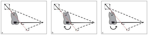
Fig 5-6 Direction of force in a high-pull headgear is backward and upward. (a) Force passing through the center of resistance causes translation. (b) Force passing below the center of resistance causes clockwise rotation. (c) Force passing above the center of resistance causes counterclockwise rotation.
Adjustment to the direction of force
Because the center of resistance of the molar is a stable point, to change the direction of the resultant force of an extraoral appliance, it is necessary to change either the point of support (the neck in cervical headgear and the parietal bone in high-pull headgear) or the length or angle of the facebow. It is easier to make this change on the head than on the neck. It is nearly impossible to change the point of application of cervical headgear, but on high-pull headgear, the point of support can be moved slightly upward or downward. For example, in skeletal open bite cases, if molar intrusion is desired, the vertical vector should be as high as possible (Fig 5-7), moving the point of support higher on the head. In this case, because the vertical component of force is much higher than the horizontal, the tooth will move upward rather than backward.
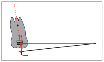
Fig 5-7 In cases requiring vertical control or molar intrusion, it is necessary to increase the vertical component of force applied by high-pull headgear. To achieve this, the point of support should be moved higher on the head.
If distal translation of the molars is indicated, the horizontal vector should be increased. To achieve this, the line of action of the force must pass between the parietal bone and the neck (the support points of high-pull and cervical headgears). When applying these types of extraoral appliances (called straight-pull or combined headgear), the resultant of the upward and downward force vectors must pass through the center of resistance of the molar (Fig 5-8).
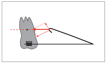
Fig 5-8 A straight-pull headgear, which is a combination of high-pull and cervical headgears, can be used when distal translation of the molar is desired.
In practice, translation of molars is a fairly difficult movement because of the difficulty in determining a tooth’s center of resistance, which is theoretically accepted to be at the trifurcation of a three-rooted tooth. Two practical methods can be suggested to determine this point. The first one is to mark the position of the molar on the cheek simply by visual determination. The second is to mark it on the cephalometric film taken by applying a thin ligature wire between the outer arm and the point of application (ie, the neck for cervical headgear and the occipital bone for high-pull headgear) while the facebow is in the mouth. Intraoral adjustment of the facebow can be done by measuring the distance between the line of action (the ligature wire) and the center of resistance on the cephalometric film.
Stay updated, free dental videos. Join our Telegram channel
VIDEdental - Online dental courses


