CHAPTER 9
Cone Beam CT-Guided Dental Implant Surgery
Christopher J. Haggerty
Private Practice, Lakewood Oral and Maxillofacial Surgery Specialists, Lees Summit; and Department of Oral and Maxillofacial Surgery, University of Missouri–Kansas City, Kansas City, Missouri, USA
The placement of dental implants with the use of custom guides generated from specific computed tomography (CT) scanning protocols and software.
Indications
- Placement of dental implants where bone height, width, or shape is limited
- Placement of dental implants near anatomical structures (inferior alveolar nerve, mental foramen, etc.)
- Flapless implant surgery
- Placement of dental implants in areas of bone atrophy resistant to grafting
- Placement of multiple dental implants
- Placement of dental implants in areas of significant adjacent root dilacerations
- When ideal prosthetics are required for the aesthetic zone
Contraindications
- Insufficient bone height, width, or shape for the placement of dental implants
- Poor bone quality
- Systemic issues (previous radiation therapy, intravenous bisphosphonates, and chronic immunosuppression)
- Bone pathology, infection, and gross periodontal disease
- Skeletal immaturity
- Psychological disorders
Technique
- Patients are consulted regarding implant and grafting materials, potential complications, the implant-to-crown timeline, the workup and surgical procedure, the healing period, and realistic final results.
- A cone beam CT (CBCT) scan, dental models, and a bite registration are taken. Any intraoral scanner that exports stereolithography (STL) files can be used. Additionally, scans of the stone models can be utilized if intraoral scanners are not available.
- The CBCT and STL files are merged using surface-mapping technology (see Figures 9.3 and 9.23 [all figures are in Case Reports 8.1 and 8.2]). The patient’s bony anatomy, soft tissue anatomy, and teeth are evaluated in a layered 3D environment. Anatomical structures are highlighted (mandibular canal, mental foramen, and sinuses).
- Implant treatment planning is performed virtually using restoration-guided implant planning (a crown-down approach) (Figures 9.2 and 9.22). Most software programs contain the majority of commercial-grade implants preloaded within their software package. The implant (or implants) is selected and is placed within the edentulous region. Manipulation of the implant position is performed with the aid of axial, sagittal, and coronal views; serial slices; and custom cross-sections. The surgeon must be cognizant of the location of vital structures, the opposing dentition, and the anticipated location of the final crown. The decision is made as to whether the crown would be best restored with a screw-retained or cement-retained prosthesis. For screw-retained prostheses, implants are planned palatal so that the screw can be positioned along the cingulum of the crown. For cement-retained prostheses, implants are centered parallel to the long axis of the crown. If multiple implants are to be placed, the implants should be placed as parallel as possible, and spacing should be optimized. Most programs have paralleling tools for this type of application.
- The final 3D treatment plan is approved, and a surgical guide is fabricated (Figures 9.4 and 9.24).
- The guide is placed prior to the administration of local anesthesia to ensure a proper fit (Figures 9.5 and 9.26). The guide should interdigitate with the occlusal third of the clinical crowns, should be rigid, and should not rock or bend. Any potential for movement of the surgical guide will be translated into drilling errors and unplanned implant placement.
- Local anesthesia is administered in the form of infiltration only. Sedations and nerve blocks are typically not utilized for mandibular implant surgery as the vibration of the drill as it nears the inferior alveolar nerves adds an additional layer of safety during mandibular osteotomy preparation. Depending on the clinical situation and the operator’s experience, the decision is made for creating a mucoperiosteal tissue flap or performing flapless surgery.
- In flapless surgery, the guide is placed, and the appropriate drill sleeve is placed for the pilot drill (Figure 9.6). The pilot drill is taken to the predetermined depth using drill stops and/or external measurements. The surgical guide is removed, and a parallel pin (or pins) is placed to confirm the depth and angulation of the osteotomy (Figure 9.7). The patient is asked to partially bite down in order to assess the placement of the parallel pin (or pins) against the opposing dentition. If the parallel pin (or pins) position does not correlate with the presurgical work-up, a periapical radiograph or CBCT may be taken to confirm parallel pin position prior to enlarging the osteotomy.
- The parallel pin (or pins) are removed and the surgical guide is placed. The osteotomy is enlarged to the preplanned size using sequential drill sleeves and drills with copious irrigation.
- Once the preplanned implant osteotomy depth and diameter are reached, a bone probe is placed into the osteotomy site in order to confirm 360° of bone contact around the circumference of the osteotomy site.
- Based on the surgeon’s preference and the guide design, the implant may be placed with the guide in place or removed.
- Based on the bone quality, either a cover screw, a healing abutment (Figure 9.9), or a provisional prosthesis (Figure 9.11) is placed. For anterior cases, immediate or early loading with prefabricated temporary crowns is recommended to shape tissue architecture.
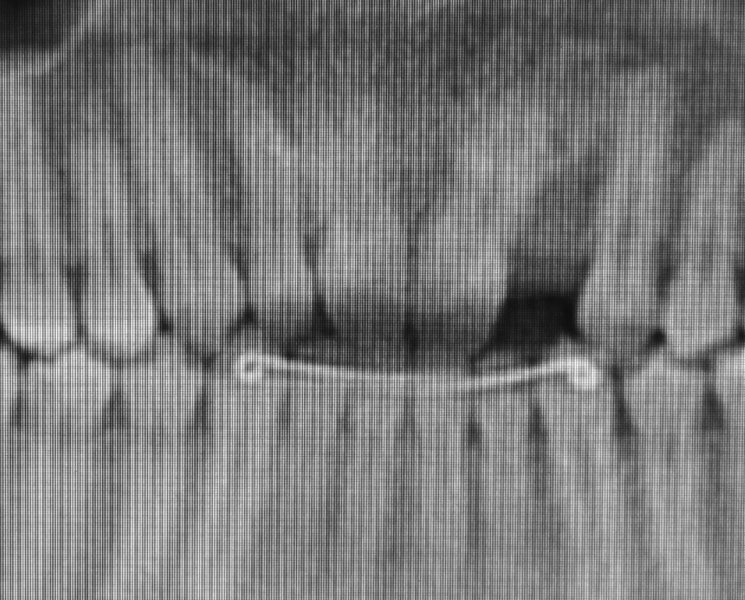
Figure 9.1. Limited mesial-distal space to site #10 due to severe dilaceration of the central incisor. Note contralateral peg lateral #7.
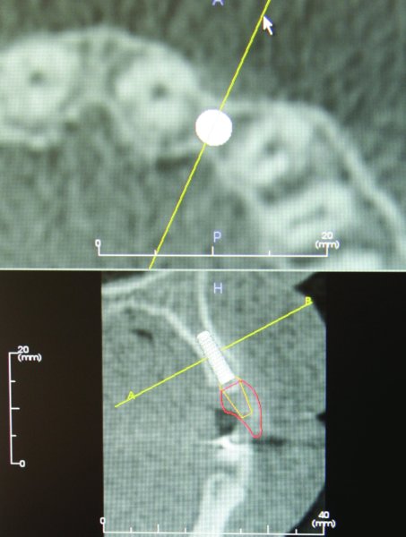
Figure 9.2. Alveolar bone atrophy associated with congenitally missing lateral incisor. Restoration-guided treatment planning is performed using implant-specific software (Anatomage, Los Angeles, California, USA).
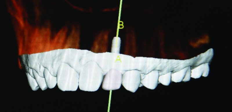
Figure 9.3. The white area represents the surface topography of the dentition and adjacent soft tissue collected with the i-Tero intra oral digital sca/>
Stay updated, free dental videos. Join our Telegram channel
VIDEdental - Online dental courses


