Resin Restorative Materials
In efforts to achieve an ‘invisible’ repair of teeth a great deal of work has been done on polymer resin–based restorative materials. While there have been many types of polymer explored and marketed for this purpose, they have all been derived from the simple vinyl, free–radical polymerized methyl methacrylate model, whose basic properties therefore underlie the behaviour of these materials.
There is, however, a range of deficiencies of chemical, physical and mechanical kinds that have encouraged the development of many modifications. The nature of those deficiencies in the context of restorative materials is now set out, and some of the attempts that have been made to overcome them are described.
The mechanical and physical problems are largely addressed through the incorporation of fillers to create a composite structure. The effects of fillers are of such a general nature that they account for the nearly–universal occurrence of composite structures in dental materials. The principles and behaviour exemplified by the filled resin materials can therefore be applied to understanding the properties and the handling of all of those other products.
The chemistry of the polymer can also be modified to reduce the disadvantageous effects otherwise obtained with PMMA. That is, by the choice of polymer backbone structure and density of cross–linking, the mechanical properties can be adjusted. This is the issue of polymer design, a matter that has implications in several dental materials areas (such as impression, tray and suture materials), and will become increasingly important in the future. Choice of product may depend on an understanding of the benefits versus the cost of such differences.
Although the use of fillers overcomes or reduces many problems, one deleterious effect arises directly: difficulty with mixing. To avoid this, command set materials are now commonplace, employing light to initiate the setting reactions. Correct handling and use depends on an understanding of these aspects.
Resin–based restorative materials are a significant part of modern dentistry. Both existing products and the likelihood of future developments place considerable emphasis on comprehension of the general principles set out in this Chapter for proper selection, handling and use.
Although silver amalgam has served as a convenient and durable direct restorative material for over 150 years, the fact that it does not look like tooth material is often now considered a major disadvantage. There are also concerns (essentially unfounded) that the mercury in it is a source of generalized toxic effects. However, environmental concerns over waste disposal are a cause to be taken seriously. Considerable effort has therefore been expended on the design and development of tooth-like materials, for restorations that are undetectable to a casual inspection. One of the main ideas in this endeavour is that of the polymer resin-based restorative (the other is that of the ion-leachable glass: silicate cement, now obsolete, and glass ionomer cement, 9§8). Again, it is found that there is no ideal solution of this kind to the problem, and a number of compromises are involved.
§1 Direct Acrylic Resin Restorative Materials
The direct fabrication of a polymer resin restoration in situ is feasible because the polymerization of methyl methacrylate can be made to proceed at low temperatures with the aid of a suitable activator (5§3). Such ‘cold-cure’ resins extend the applications of acrylic polymers away from denture bases and related areas. They are usable in the mouth because the temperature rises involved during reaction are low enough not to pose an overt hazard to a vital tooth (due to the small volume of a typical restoration, heat is lost quickly), and the setting reaction rate can be made high enough that chair-time is kept within reasonable limits. In fact, so-called light-cured materials are even more convenient. But now, to examine the successes and failures of this line of development, a semi-historical account will be given.
•1.1 Unfilled acrylic
The earliest materials used were plain and simple, unfilled, poly(methyl methacrylate). This was in effect just cold-cure acrylic resin, but with colouring more appropriate to tooth tissue. The technique consisted of moistening a small brush with monomer, and then using that to transfer a small amount of the PMMA powder to the cavity. The polymerization reaction would already have started in that first increment when the next portion was added, and so on until the cavity was filled. Benzoyl peroxide could still be used as the initiator, being a relatively cheap source of free radicals. However, the amine activators ordinarily used (5§3.2) are aromatic, and have conjugated systems of π-bonds which absorb ultra-violet light (24§6.2) to create high energy states. Such activated molecules or side-groups to the polymer chain can react with oxygen, which would be dissolved in the resin from the air, or with other aromatic groups, or even with small organic molecules derived from foodstuffs which could diffuse into (i.e. dissolve in) the polymer, to form larger, more extended conjugated systems. The creation of these larger systems – colour centres or chromophores – pushes the absorption of light into the visible region, starting with the blue, with the consequence that the resins become yellowish (24§6.2).
The colour stability of such a resin is more critical for restorations than for denture base materials because of the general paleness and translucency required to match tooth tissue. Since some ultra-violet light illumination is unavoidable (from sunlight, Fig. 24§4.2, as well as fluorescent lighting, 24§4.9, and quartz-halogen lamps, 24§4.3), especially in the anterior regions of the mouth, such restorations would quickly become obvious and unacceptable. One possibility is the use of ultra-violet absorbing molecules, intended to play no part in the polymerization reaction, much as such absorbers are used in commercially-produced bulk polymers (then called UV-stabilizers) or as are used in sun-screen products for our skin. However, these were found to be of limited value, and it was therefore necessary to find alternative activators.
•1.2 Activators
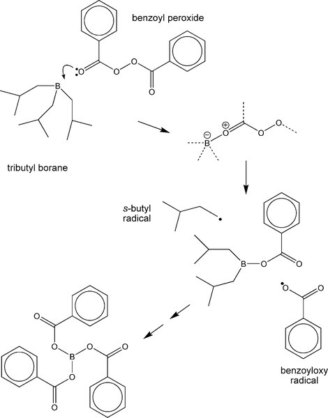
There are a variety of chemical systems which have now been found to be workable as activators in the dental context, more or less overcoming the colour stability problem. For example, tributyl borane and the sodium salt of p-toluene sulphinic acid have been used as these do not form such coloured compounds so readily. Alkyl boranes (Fig. 1.1) readily form adducts with electron donors – such as benzoyl peroxide. These polar compounds are unstable and so they then rapidly decompose, generating two radicals which may be active in the initiation of polymer chains. The resulting boron ester compound continues to be active until the tri-benzoate ester has been formed. The essence of this sort of reaction is only that of encouraging the dissociation of the benzoyl peroxide. However, it may be noted that the boron tribenzoate is a small, polar, organic molecule: it is therefore (a) a plasticizer, (b) going to encourage water absorption, and (c) potentially leachable. As in many areas of materials design, there is a compromise: the mechanical properties of such a material will not be quite as otherwise expected. Even so, there are several serious drawbacks to using such a resin system as PMMA as a restorative material.
•1.3 Polymerization shrinkage
This is of the order of 21% by volume for polymer from pure methyl methacrylate. It was partly overcome by using beads of polymer to the extent of about three-quarters of the initial mixture, as in denture fabrication or the use of cold-cure materials elsewhere. However, the 5% shrinkage which remains demanded that special techniques be used if its effects were to be minimized. Minimized, perhaps, but not eliminated, since the polymerization must continue for some time after the initial ‘setting’, that is, when the material is apparently hardened. The shrinkage correspondingly proceeds at about the same rate. Such shrinkage led to marginal leakage, discolouration, sensitivity, and secondary caries.
•1.4 Thermal expansion
The coefficient of thermal expansion of polymers in general is very large, about 70 MK-1 for PMMA, and very much larger than that of enamel (11 MK-1) or dentine (8 MK-1). Consequently, even the modest excursions of temperature normally experienced in the mouth will produce marked relative dimensional changes of the restoration in the tooth. This might not be so bad if it were reversible.
Shrinkage on cooling will open a gap at the periphery and permit the percolation of oral fluids, with the possible consequence of a brief period of pain and some discolouration at the margin. Rewarming to normal temperatures would be expected to close the gap again. On the other hand, expansion due to higher temperatures than normal would result in a rise in the pressure in the material, if – as is intended to be the case – there is contact between the filling and the cavity walls. This pressure will tend to be relieved by plastic flow or creep (1§11), an extrusion of the resin beyond the original margin (Fig. 1.2). This permanent deformation may only accumulate slowly, as the viscosity of such a polymer even a few degrees above mouth temperature would be very high, but it would be enough to ensure that on cooling it would leave a progressively larger and persistent peripheral gap. Subsequent cooling would therefore expose a larger than expected gap, and clearly could not undo the damage already done. The dimensional change of cooling (by itself) is recoverable for a simple, one-surface restoration; that of heating will not be entirely recoverable. In more complicated cavity designs, involving two or more surfaces, or a narrow isthmus, other forms of distortion will occur, as stress relaxation must proceed for both heated and cooled restorations. Distortion or extrusion would also expose edges to extra wear. A key requirement for an ideal restorative material is thus the matching of its thermal expansion coefficient to that of enamel.
•1.5 Strength
The strength of PMMA, a polymer, is relatively low compared with enamel, a ceramic composite, and a relatively large bulk of resin would be required to withstand masticatory forces in the absence of supporting tooth tissue. However, the abrasion resistance is very much lower than that of tooth and wear occurs readily, due to the abrasiveness of foodstuffs, opposing dentition and toothpaste. The consequent relief of the restoration surface leaves the enamel margins exposed and thus prone to chipping and as enhanced abraders of an opposing tooth. Differential wear should therefore be avoided.
•1.6 Stiffness
Young’s Modulus for acrylic resins is very much lower than that of enamel and so the deformation on loading is greater. Such differences in strain also cause shear stresses to appear at the interface, and while a simple retention form may have been used for such restorations, i.e. an undercut design, such shear would also tend to damage any micro-mechanical key. Elastic modulus matching is thus a further requirement of an ideal material.
•1.7 Yield
In addition, because polymers tend to be plastic (4§7.3) – as is implied by the use of that term as their common name – and with a low yield point, ordinary masticatory stresses applied in service may cause permanent distortion and extrusion, slowly but cumulatively, resulting in deleterious changes to the peripheral fit with consequent leakage and therefore pathology. This is interrelated with the issues of thermal expansion and strength, discussed above, for effects after extrusion.
•1.8 Water absorption
For polymers such as PMMA, which have polar substituents, water absorption has two important effects:
(1) it produces a swelling which will exacerbate the extrusion mentioned above due to heating, and
(2) since water is a plasticizer, making the resin softer (lower elastic modulus and lower viscosity), it therefore increases the deformation to be expected during such episodes of stress. The strength is also reduced.
Exposure to water plainly cannot be avoided in the mouth.
•1.9 Appearance
This is obviously of keen interest if indeed the tooth material is to be mimicked and the restoration be invisible to casual inspection. Well-prepared polymers such as PMMA are optically clear, and indeed this polymer is used for spectacle lenses and aircraft windscreens, and some modified types as contact lenses. Teeth obviously are relatively opaque, scatter light, and are somewhat coloured. The latter can be dealt with by adding dyes, but the other properties remain to be addressed (see 24§5.11).
•1.10 Radio-opacity
The radiographic appearance may also be a problem. Being composed of light elements, X-ray absorption is slight (26§3) and PMMA and other organic polymers are essentially radiolucent. This means that they are impossible to detect in radiographs, and so distinguishing restoration from pathological effects (caries) may be hard. This problem also arises in a more life-threatening manner in the context of inhaled PMMA denture fragments, as well as with inhaled, swallowed or otherwise internalized plastic toys and parts in children: locating, let alone recovering them, may be very invasive, and although magnetic resonance imaging (MRI) can handle such problems, its cost puts it out of the reach of routine work.
•1.11 Mixing
This is a general problem affecting any product where reaction commences immediately on contact between reactants. Restorative materials must set in a reasonably short time to be practical. This implies high reactivity at room or mouth temperature and therefore little time for mixing and placement. Questions of the homogeneity of the mixture, and thus of the uniformity of properties if not the completeness of setting, of the accuracy of proportioning to attain the correct outcome, as well as of the incorporation of air bubbles, must all be considered. The fact that small amounts are used does not make this any easier.
•1.12 Reaction exotherm
Polymerization and cross-linking reactions are exothermic, i.e. they raise the temperature of the material above that of its surroundings, aided by the poor thermal conductivity of polymers. This may have two consequences. Heating and thus irritation and inflammation of underlying pulp or odontoblastic processes might lead to post-operative pain or discomfort,[1] and secondly, thermal expansion of the restoration (§1.4).
•1.13 Composites
All of these points explain the lack of success of a plain acrylic restoration. Clearly, modifications to the polymer itself (size and polarity of substituents, for example) could only have limited effects, and only in some areas because of the very nature of organic polymers. However, the addition of a stiff, inert, radiopaque and optically-suitable (24§5) filler to any such resin is instrumental in producing much larger and more useful changes in some properties, and goes a considerable way in ameliorating those inherent difficulties. Such materials are said to have a composite structure, a mixture of (at least) two materials with differing properties of one kind or another. The properties of the composite are intermediate in many senses to those of the components, and effective compromises are possible, utilizing one or more aspects of each component to advantage when individually they would be unusable or unserviceable, as indeed we have now found plain resins to be in a particular context. Nevertheless, we do find that there is compromise, as one gain is traded against another loss.
It is, however, appropriate here to draw attention to the fact that most materials in dentistry are composite in structure, and that the term ‘composite’ is not in any way restricted in application to these particular resin-based restorative products. Thus, all cements are composite, consisting of a core of unreacted powder in a matrix of reaction products (9§4); amalgam is a composite, unreacted original alloy is embedded in a metallic matrix of reaction products (14§5); all flexible impression materials (except some agar products) contain a finely particulate filler to modify viscosity and stiffness (7§3); carbide-containing alloys such as steel and cobalt-chromium as well as cermets (21§3), casting investments, porcelain, and so on, all include more than one discrete and recognizable substance; skin is composite; teeth are composite. We could, without stretching the point too far, describe PMMA prepared from powder and liquid as composite. The polymer created from the liquid, as a matrix for the commercially prepared powder, must have (slightly) different mechanical properties because the polymerization conditions are different (5§2). Similarly, dental waxes, since they consist of a mixture of crystalline core and amorphous matrix (16§1), are also composite, even if the compositions of the two regions are similar. A trivial case would be that of dental plaster: a dihydrate matrix with a core of air or aqueous solution. It is still a clearly two-part structure. Since the overall behaviour depends on the structures and behaviours of the components, one approach to such systems is to consider the combination (Table 1.1). However, some care is required in applying a simple scheme such as this: such classifications are not absolute or comprehensive – there are other combinations and variations possible.
It is, therefore, not actually wrong in any way to refer to filled-resin restorative materials as ‘composites’, but it is certainly wrong to use the term as if it applied only in that very limited connection: such a usage is quite incomprehensible outside of dentistry, where the design and study of composites such as boron fibres in metal alloy matrices is central to much ‘high performance materials’ research. Within dentistry the usage devalues the scientific meaning of the term and draws attention away from the fact that so many dental other materials are of this kind of structure, and that their behaviour and properties all can be understood in precisely the same terms no matter what the composition or application. Whilst it is true that the phrase ‘filled–resin restorative material’ is a little long, it is at least the minimum acceptable, accurately descriptive term. The short-hand form ‘filled resin’ will suffice here because the immediate context is taken to be understood, but the mechanical properties must be discussed in terms of the general theory of composite structures. It will be understood, therefore, that much of what is said here also applies in one form or another to all of those other materials, in dentistry or outside, whether technical or commonplace, natural or artificial, food or fabric.
§2 The Effects of Fillers
The effects of the rather large polymerization shrinkage of PMMA can be reduced by adding a proportion of already polymerized material (5§2.4). The overall shrinkage that is then observed is in direct proportion to the volume fraction of the polymer newly produced (or, of the mole fraction of monomer added, reckoning the added polymer in terms of mers). However, even relying on this, as did the early direct-filling acrylic materials (§1), the shrinkage is inconveniently large. Similarly, the amount of heat released during the polymerization reaction is reduced in proportion, as the number of bonds to be formed is reduced. This kind of effect clearly also applies no matter what the ‘filler’ is, PMMA or other material, but such properties as the water absorption and thermal expansion are quite unaffected if it is PMMA that is used. However, if a non-absorbent filler were to be used, the overall water absorption would be similarly proportionately reduced (although the absorption by the polymer itself must remain unaffected). This is an interesting lead, and the effects of such fillers on properties such as thermal expansion, strength and modulus need to be explored, for it is not at all obvious that similarly simple relationships apply. We return to this topic below.
•2.1 Thermal expansion
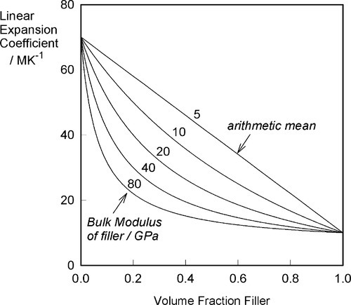
If the filler is chosen to have a coefficient of thermal expansion lower than that of the matrix, experimentally it is found that the relationship with proportion used is not that of a straight line, as would perhaps be expected on the basis of an arithmetic mean effect (Fig. 2.1). The observed behaviour indicates a greater effectiveness for the addition of the filler than its volume fraction would suggest. The explanation for this can be found in the mechanical interaction of the two components.

The defining equation of the coefficient of volumetric thermal expansion, β, is:
< ?xml:namespace prefix = "mml" ns = "http://www.w3.org/1998/Math/MathML" />

where ΔT is the temperature interval over which the change in volume, ΔV, is measured (see also 17§1.1), while that of the bulk modulus of elasticity (1§2.6) was given by (equation 1§2.23)
so, substituting from 2.1, we have

This is the stress that would be obtained in a particle trying to change dimension against a perfect constraint, i.e. embedded in a rigid, non-expanding environment when there is no actual volume change at all. That is, a particle in this situation would be squeezed by the matrix – hence the use of the bulk modulus. However, we must allow for the fact that the matrix will also be changing dimension to some extent, so that the effective coefficient of expansion to be used in that equation will be given by the difference (βc – βi), where βc is the overall expansion coefficient, and i = 1, 2, … identifies which of the n components is of interest. Thus, the stress in any component of the filled resin system (and this is true for any particulate composite material) is therefore given by:
That is, the (hydrostatic) pressure locally depends simply on the difference between the local and the overall expansion coefficients. However, if the body is under no externally applied constraint or load, the overall mean hydrostatic pressure must be zero (for if it were not, the dimensions must change until equilibrium were achieved). Thus, summing over all i components:
because tension and compression are taken to have opposite signs (ϕ is volume fraction, as before, 2§2). Once again, this is Newton’s Third Law of Motion being invoked: if there were to be a non-zero resultant force, something would have to move until equilibrium were established. Hence, from 2.5 and 2.6, and in the simplest case of one filler in a continuous matrix (n = 2), we can write:

which rearranges to show that
which is a kind of weighted mean.
What this analysis shows is that the overall thermal expansion depends not only on that of the components, and their volume fractions, but also rather critically on their bulk moduli, their compressibilities (Fig. 2.2). We may also notice from equation 2.5 that as one of β1 and β2 in a two component system must be greater, and the other lower, than βc, the stresses in the two components must ordinarily be in opposite senses, there being only one temperature at which the stresses are both zero. The presence of such stresses has implications for the interface between the components: these must be under stress too. The importance of this we return to below.
Ceramics, which are usually stiff, hard and strong, and therefore apparently suitable as strengthening fillers, typically have coefficients of expansion about one tenth of those of typical polymer resins (Fig. 3§4.14). Indeed, at least one is known and used in dentistry with a negative coefficient over the temperature range of interest.
If, as is obviously intended to be the case with filled-resin restorative materials, the filler has a lower expansion coefficient than the resin matrix, raising the temperature could not develop a stress across the interface if there were no bond between matrix and filler. The matrix would expand unhindered (Fig. 2.3) as there can be no restraint, and the previous equation would be inapplicable. The filler particles would be loose within the matrix and just rattle around as the holes get relatively bigger. There would thus be no effect whatsoever on thermal expansion on heating due to the filler. Indeed, the filler could be absent altogether (equivalent to having pores or bubbles in the resin) and not be noticed as missing from this point of view.
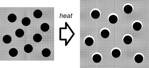
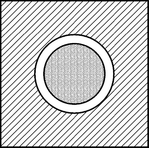
•2.2 Matrix constraint
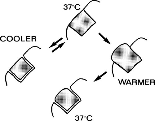
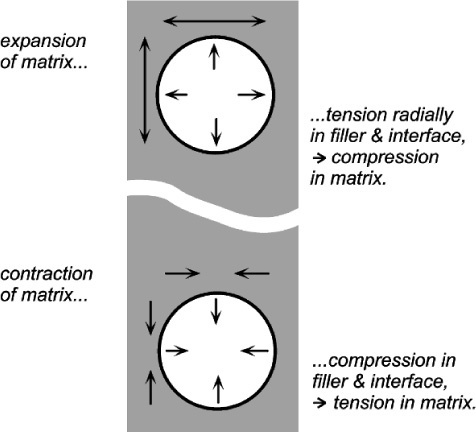
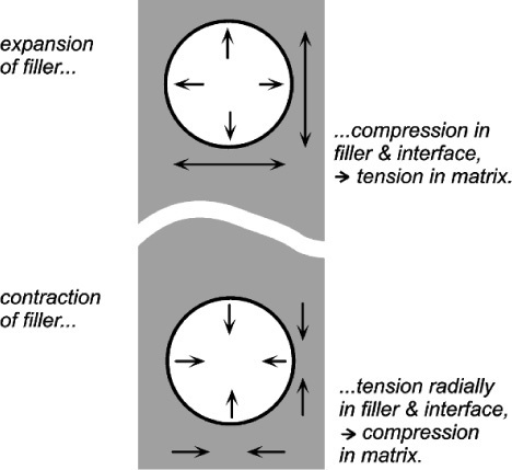
If the matrix of such a system has expanded, in order to return to it contact with the filler it must be hydrostatically compressed (Fig. 2.4). Thus, when there is bonding, and the temperature is raised, the filler particles would be put in tension (as must be the interface between the two itself). To balance the stresses, the matrix must then be in compression (Fig. 2.5, top). This ‘holding back’ of the expansion of the matrix, or matrix constraint, due to interfacial bonding is thus absolutely crucial to the effectiveness of a filler for this purpose of modifying thermal expansion behaviour. On cooling such a material, i.e. with β(matrix) > β(filler), the stress at the interface becomes compressive (Fig. 2.5, bottom) and the nature of the interface, whether bonded or not, is quite irrelevant. The stresses within the matrix are now tensile while the core is in compression (Fig. 2.6) (see also 18§4.6).
There are limits to this. If the cooling is extreme these stresses may result in cracking within the matrix, that is when according to equation 2.5 the strength of the matrix material has been exceeded. Similarly, on heating enough, the stress at the bonded interface of matrix and filler may exceed its strength. The resultant bond failure would then render the filler ineffective from that point on. Of course, outright failure is not the only possibility with polymeric matrices, and stress relaxation through flow processes might complicate the picture (see box).
In fact, if the flow effects dominated, the overall volumetric thermal expansion coefficient would approach the arithmetic mean (i.e. weighted by volume fraction):
This equation would apply to a system such as sand in water. The line representing this equation is shown in Fig. 2.2 for comparison, but it is emphasised that it is not the proper equation for a bonded, particulate-filled composite except if the bulk moduli happened to be identical, when equation 2.8 reduces to the form here.
If visualizing how an expanding matrix produces compression in itself when bonded to the filler causes any difficulties, consider the entirely equivalent situation of a contracting filler (Fig. 2.7, bottom). Clearly, the interface is in tension again, but the squeeze exerted on the matrix is now perhaps more obvious. Again, if the filler were to expand it would put the matrix into tension as it was obliged to stretch over the now larger insert (Fig. 2.7, top). This latter situation is the case in the rusting of reinforcing steel in concrete: the expansion bursts the concrete. It is also the situation in impression plaster when this contains starch (27§2.4). The point is that these systems are symmetrical: if one case can be worked out, the others follow automatically by reversing the signs of all the stresses.
Similar considerations apply in mechanical testing machines. If the specimen in Fig. 1§3.6 is in tension, then the side columns, supporting the two fixed crossheads, must be in compression. The point is that all stresses occur in pairs if static equilibrium is to be observed – Newton’s Third.
•2.3 Polymerization shrinkage
In a filled material, polymerization shrinkage leads to a similar condition as does cooling (Fig. 2.5, bottom). While the matrix is still relatively plastic and not cross-linked enough, viscous flow would permit the relief of the stresses that this shrinkage causes. However, at some stage, the viscosity will become sufficiently high that this cannot happen fast enough. Hydrostatic tensile stresses then begin to develop within the matrix, increasing (asymptotically) as the reaction proceeds, with cross-linking and viscosity rising, until the reaction and the flow come effectively to a halt. The system is then described as stress frozen. Under these conditions, and assuming that the rate of reaction has been uniform over the whole volume of the material, the system looks as though it had been cooled – the volume of the matrix would, at equilibrium, have been decreased, but the presence of the filler has prevented this. The matrix is therefore in tension. The temperature of the fully-set material must then be raised by an amount sufficient to reduce these tensile stresses to zero before further heating causes the interface stresses to change from tension to compression.
The polymerization reaction exotherm is also relevant. Thus, when the cross-linking has proceeded to a stage where viscous flow is much impeded, the temperature may be near its maximum. This may be only a few degrees above 37°C, say, but this effect would contribute to the residual tensile stress in the matrix on cooling to ‘normal’ mouth temperature, adding to that stress produced by the polymerization shrinkage. Clearly, whether there is a net hydrostatic tension within the matrix when it is fully set and cooled to its working temperature depends on the balance between the rate of relaxation through viscous flow and the rate of cross-linking. Unfortunately, since it is a dynamic system, detailed calculations are not feasible. However, it seems likely that there does remain some hydrostatic tension in the matrix of the fully set material. The main evidence for this is that polymerization shrinkage as a bulk phenomenon affecting the fit of restorations is still serious enough to need to be taken into account with modern materials. Hence the use of incremental ‘wedge’ techniques and similar procedures to minimize the stress placed on the bonded interface between restoration and tooth.
•2.4 Water sorption
The oral environment is wet – internally and externally. To understand polymer behaviour in service in such circumstances, we must therefore consider the effect of water sorption. As already described (5§6), PMMA and similar polymers with polar groups will absorb appreciable amounts of water, one or two percent being typical. This water has two principal effects, which apply in the present systems as much as anywhere. There is the plasticizing effect: the lowering of modulus and increase in flow rates due to the increase in effective free volume for chain segment motions. There is also a volumetric expansion as the absorbed molecules do not just fit into available space, but allow the polymer chains to move further apart as well. The resulting expansion would also be expected to operate as does thermal expansion in terms of the stresses generated (Fig. 2.5, top). This absorption, and thus the expansion, will occur after setting is largely complete (because ‘setting’ for clinical purposes takes only a matter of a minute or two) because it is only then that exposure to water or saliva will occur. But it is still expected to take several days even to approach equilibrium because the diffusion of water through resin is a slow process.
How much such expansion actually compensates for polymerization shrinkage is uncertain, but the existence of the effect illustrates the complexity of the analysis of such systems in service. For example, if the absorption expansion exceeds the polymerization shrinkage, then the restoration would fit, but would suffer extrusion as in Fig. 1.2, even without warming. Also to be taken into account is the fact that the ‘open mouth’ tooth temperature during clinical work may be several degrees below that of the normal situation. Thus warming of the material after completion of the clinical work should also be taken into account.
A non-absorbent filler is expected to reduce the overall water absorption of the composite material in direct proportion to its volume fraction, i.e. the absorption, Wc, is in direct proportion to the volume fraction of the resin (ϕm) doing the absorbing, given the absorption, Wm, of that matrix resin itself:
Unfortunately, if the interface between resin and filler is not well-bonded, or is subject to hydrolytic breakdown (§2.15), this region can itself hold water, increasing the total absorption above that of this simple expectation.
•2.5 Elastic modulus
The effect of fillers on the modulus of elasticity is of very great importance in the general field of composite materials. We shall return to it in particular in the context of impression materials (7§3), but since nearly all materials used in dentistry are composite, this is perhaps the single most important aspect.
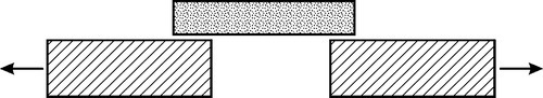
Given the (differing) mechanical properties of two homogeneous and isotropic components (Fig. 2.8), the problem is one of how to calculate the mechanical properties of a composite of the two. The typical case in dentistry is of a particulate filler in a continuous matrix, but since this is too difficult to handle theoretically we shall use a simpler system, the so-called ‘sandwich’ model, consisting of alternating layers of the two components. Having done that, there is clearly now a directionality to the structure that must be taken into account (Fig. 2.9). More than that, the sandwich composite is fairly obviously going to be anisotropic, that is, generally have different properties in the two load directions.
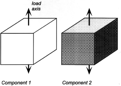
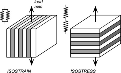
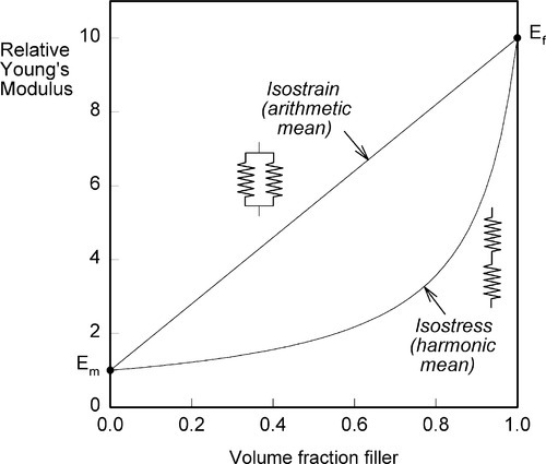
If the elements of the structure are in parallel and aligned with the load axis, the strain of each element is by definition identical since we are assuming that the end faces remain plane and normal to the load axis. (We imagine that the loading is applied over the entire upper and lower faces of the block by a perfectly rigid and flat anvil.) This then is known as the isostrain model (sometimes also called the Voigt model – not to be confused with the Kelvin-Voigt model of retarded elasticity, 4§5 – elements in parallel is the common idea). However, the resulting stresses in the two components must be different because the material with the lower modulus requires a lower stress to be extended by the same amount as the stiffer component.
For the alternative orientation, where the layers are normal to the load axis, and therefore connected in series along the load axis, the stress acting on each must be identical. If the elastic moduli of the layers differ, necessarily they suffer differing strains. This isostress model (also known as the Reuss 1 model) thus represents the opposite extreme of the orientation of the structure with respect to the load axis.
•2.6 Rules of mixtures
The overall modulus of elasticity of the composite in the direction of loading can be calculated in the two cases using the relevant so-called rules of mixtures.[2] These are no more than the arithmetic or harmonic mean of the individual components’ elastic moduli, weighted according to their volume fractions. The derivations of these are quite straightforward.
Thus, for the isostrain model, we have by definition
where εc is the overall strain on the composite body. But the overall stress on the composite σc must be distributed according to the volume fractions of the two components (which can be seen to be the same as the area fractions in a cross section):
This is the principle of uniformity again (1§2.1). But now we can replace the stress according to Hooke’s Law (equation 1§2.4 a):
Therefore, because the strains are identical (equation 2.10),
i.e., the overall modulus of elasticity for the isostrain case is given by the weighted arithmetic mean of the elastic moduli of the components (since ϕ1 + ϕ2 = 1).
For the isostress system we have now, again by definition,
The overall strain is therefore given by
Again, we make the substitution from Hooke’s Law, this time for the strain:
Therefore, because the stresses are identical (equation 2.14), we have
Solving this for Ec gives:
i.e., the overall modulus of elasticity for the isostress case is given by the weighted harmonic mean of the elastic moduli of the components. This is the same as the weighted arithmetic mean of the compliances, J = 1/E (see equation 1§2.4 c):
This can be understood by noticing that the deformation of each layer is assumed to be completely independent of that of the other layers, i.e., no shear stresses at the interfaces due to Poisson deformations, that is to say that v1/E1 = v2/E2 must hold if the lateral contraction in the two kinds of layer is to be the same. Actually, the same assumption of independence is also made for the isostrain case, equation 2.13, which is equivalent to saying that v1 = v2 if the lateral contraction in the plane of the layers is to be the same in the two component materials. Clearly, both cannot be true simultaneously unless E1 = E2, when the system is effectively reduced nearly2to a mechanically-homogeneous material and the “composite” properties are therefore unaffected according to these equations.
It is not possible to make a structure any more or any less stiff than these simple equations imply (assuming no holes, and that the layers are properly bonded in the isostress case) and thus the graphs of these functions are the upper and lower bounds to the achievable modulus of elasticity of any composite, including particulate fillers (Fig. 2.10). These are rather wide limits, and as such are not particularly useful for understanding or predicting behaviour, but they do form the basis of the development of more precise but much more complex descriptions of composite behaviour. It has to be said that there is, as yet, no complete theory, but some of the underlying principles can be identified.
The hydrostatic tension arising within the matrix due to thermal contraction has already been mentioned. If there is a perfect, non-slipping bond at the matrix-filler interface, there is a similar condition of matrix constraint by the filler during loading. That is, during the application of a uniaxial load, say in tension, a hydrostatic tension is developed because the Poisson contraction (1§2.2) otherwise expected is limited by the filler. In other words, we need to go beyond the assumption of independence of deformations that was relied upon in the derivation of the isostress and isostrain bounds.
•2.7 Apparent modulus of elasticity
Using the relationships of Hooke’s Law and the Poisson Ratio, the strain in the matrix of a particulate-filled composite in the load axis (x) direction can be derived. We shall assume, for simplicity, that there is no deformation of the filler (i.e. it has an infinite modulus of elasticity). Thus, we start with the basic results

where σx is the tensile stress (for example) in the x-direction and the subscript m refers to the matrix. We now take constraint to mean that the Poisson contraction is opposed. This is equivalent to transverse tensile stresses just large enough to achieve this being superimposed:
Stay updated, free dental videos. Join our Telegram channel
VIDEdental - Online dental courses


