5
Treatment Planning: The 3D VTO
Determining the treatment goal
Producing an occlusogram
Combining the occlusogram with the head film
The computerized occlusogram
Responding to patients’ needs
Orthodontic treatment: art or science?
References
Determining the Treatment Goal
Once a patient decides to have treatment, the detailed treatment planning can be carried out. However, before the necessary appliance can be chosen, the treatment goal has to be established. This can be done by the work-up of a three-dimensional visual treatment objective (3D VTO), which consists of an occlusogram combined with the tracing of a head film or by simulating the desired tooth movements on virtual models. In adult patients, in whom no growth-related changes are expected to influence the treatment result, the tooth movements necessary to achieve the treatment goal can therefore be more clearly defined.
Producing an Occlusogram
Since there is no growth in the adult patient, the only available option is tooth movement. Tooth movement can be performed in all three planes of space. The horizontal, i.e. the sagittal and the transverse, movements of teeth generally contribute more to the total treatment than vertical movements. The use of the occlusogram is therefore extremely useful in these patients.
When illustrating the treatment goal in relation to an occlusogram, the orthodontist will have to:
- Define the line of symmetry in the patient
- Indicate the desired movement of the anterior teeth
- Indicate a tentative transverse dimension for both arches in the premolar and molar regions
- Choose the anterior arch form.
Once the planned tooth movements are indicated on the occlusogram, this will allow the clinician to:
- Simulate the pre-treatment occlusion
- Undertake space analysis
- Assess the changes needed in the length and the width of upper and lower arches
- Simulate the horizontal tooth movements. When combined with the head film tracing, the movement of the incisors in all three planes can be visualized. When using virtual models instead of the occlusal images of the study casts, three-dimensional simulations of all desired tooth movements can be performed
- Define the active and reactive dental units
- Evaluate the anchorage requirements
- Estimate tooth size/arch size discrepancies
- Define the force systems necessary for the planned tooth movements
- Compare the final post-treatment result with the predicted movements indicated on the pre-treatment occlusograms.
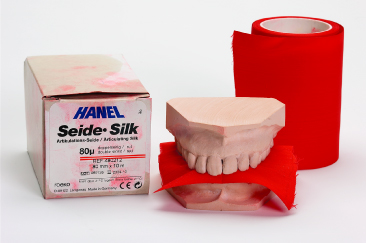
Replacement of the plaster study casts with virtual models makes it possible to simulate not only tooth movements in all three planes of space but also, when combined with 3D cone-beam imaging, orthognathic surgical interventions. The conventional occlusogram as described by Burstone and Marcotte (2000) is based on an image of the study casts or an occlusal view of virtual models. Before producing an image of the study casts they have to be placed into occlusion with a thin piece of silk (Hanel Articulating Silk®) or a wax bite to localize the areas of occlusal contact (Fig. 5.1). In the case of virtual models, occlusal contacts are already indicated on the models.
Fig. 5.1 Study casts in occlusion with red silk for localizing the occlusal contacts.
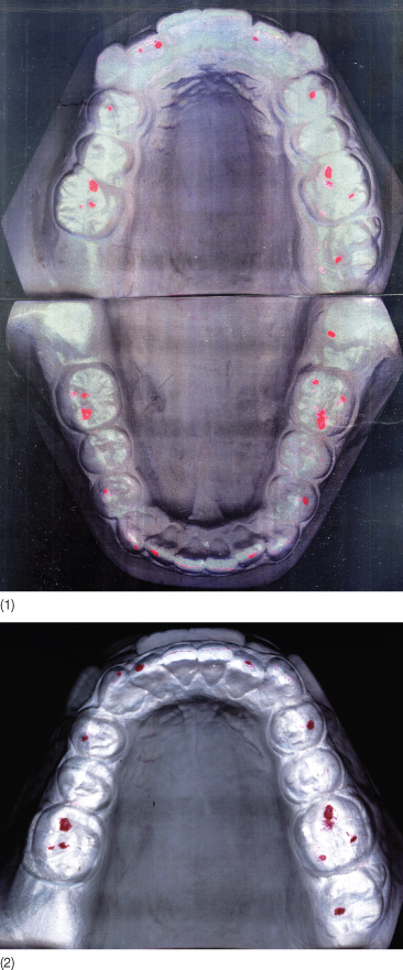
The occlusograms applied by Bjork and Skieller (1972) were produced from drawings of photographs or photocopies of the study casts. Scanning the study casts is easier and more precise, and the images can be drawn or printed on transparent paper that allows for superimposition of the upper and lower arches on the occlusal contacts (Fig. 5.2).
Fig. 5.2 (1) Occlusograms copied on transparent paper. (2) This makes it possible to superimpose directly.
When performing an occlusogram manually, the following structures should be outlined:
- The gingival contours of the teeth
- Incisal ridges and buccal cusp ridges
- Central grooves and cusp tips
- Palatal rugae and the mid-palatal raphe
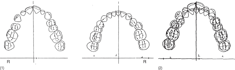
- Reference points used when superimposing the upper and the lower occlusogram (Fig. 5.3).
Fig. 5.3 (1) Hand-drawn occlusograms. (2) Occlusograms superimposed on the occlusal contacts to simulate the occlusion.
The first step when producing a VTO is to determine the position of the post-treatment dental midline on the upper or lower dental cast. For this, the arch in which the least corrections are required is selected. The anterior dental midline should if possible coincide with the facial midline, which is determined from the frontal view of the patient or from a frontal radiograph (Fig. 5.4). The facial midline is indicated as a point on the occlusogram. Once a midline has been determined in relation to one of the two dental arches, it is transferred to the other arch by superimposing the arches on the occlusal contact points (Fig 5.2).
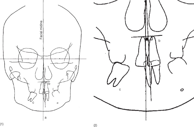
Fig. 5.4 Frontal radiograph on which bilateral landmarks and the midpoints are indicated. Note the large variation in the midpoint at different levels of the face. This variation frequently makes it impossible to construct a facial midline based on the radiograph.
(From Burstone and Marcotte 2000. Reproduced with permission from Quintessence Publishing Co Inc, Chicago.)
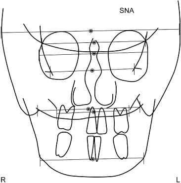
In patients without facial asymmetry, the facial midline, the dental midlines and the anatomical midline coincide and correspond with the median raphe. In the case of facial asymmetry, the future position of the dental midlines should be determined first. Burstone and Marcotte (2000) showed that defining the dental midlines based on skeletal measurement can be considered invalid as no symmetry exists between the bilateral landmarks (Fig. 5.4). Often the interpupillary line is used as reference and the occlusal plane is planned parallel to this line, as the face thereby seems less asymmetrical than if trying to adapt the dental midlines to the face (Fig. 5.5). The predicted dental midlines should correspond to the interpupillary midpoint and may be modified with regard to major asymmetries in other parts of the face, especially asymmetries of the nose.
Fig. 5.5 (1) Patient with an obvious asymmetry. The facial midline can in this case be defined as the perpendicular to the midpoint of the interpupillary line. (2) This was also done in this patient with hemifacial microsomia. (3) In this patient with plagiocephaly, the occlusal plane was aligned to the true horizontal and the dental midlines were adjusted to the nose. Note that the asymmetry is more apparent.

In addition to the dental midlines, Burstone and Marcotte (2000) described an apical base midline, defined as the midpoint between the apical part of the roots of the upper and lower incisors (Fig. 5.6). According to these authors, comparison of this midline with the dental midline, defined as the incisal contact point, indicates whether the incisors are upright or tilted mesiodistally. This can only be evaluated on a frontal radiograph or a 3D image. Once determined, the dental midlines can be represented as anterior points on the occlusogram.
Fig. 5.6 (1) Tracing of a frontal radiograph with marking of the facial and the apical base midlines. (2) The same image at a larger magnification. The midline between the apices of the upper incisors’ roots is indicated. It has also been recommended to use a point between the upper third of the roots as the shortening of one root may otherwise influence the apical midline.
The shape of the arches determines the posterior point defining the midline. The midline can be drawn corresponding to the median raphe, the anatomical midline, or the geometrical midline obtained when folding the occlusogram so that the molars on one side cover the contralateral molars, provided they are not rotated or tipped. If this is the case, a simulation of the upright, non-rotated position should be assumed.
Selection of the geometrical midline indicates that symmetrical mechanics can be applied and the difference in width on the two sides will be maintained. Correction of an arch shape that needs widening on one side and narrowing on the other side is physically not possible unless skeletal anchorage is used. Choosing the geometrical midline is in fact accepting the discrepancy in width, but this does not imply that the occlusion cannot be the same in the two sides. The canine-to-canine relationship can, as can the molar relationship be kept symmetrical in spite of the difference in width on the two sides (Figs 5.7–5.9).
Fig. 5.7 The geometrical midline can be ascertained by folding the occlusogram so that the molars of the two sides are superimposed. This can only be done if no local tooth movements have occurred. The geometrical midline can also be determined in relation to the virtual models with special software which can select two symmetrically located points in the lateral regions.
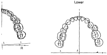
Fig. 5.8 (1,2) Study casts of a patient with asymmetry of both arches. Both arches are clearly wider on the left than on the right side. (3–5) The sagittal occlusion is neutral on both sides. (6) The right and left sides are asymmetrical anteroposteriorly.
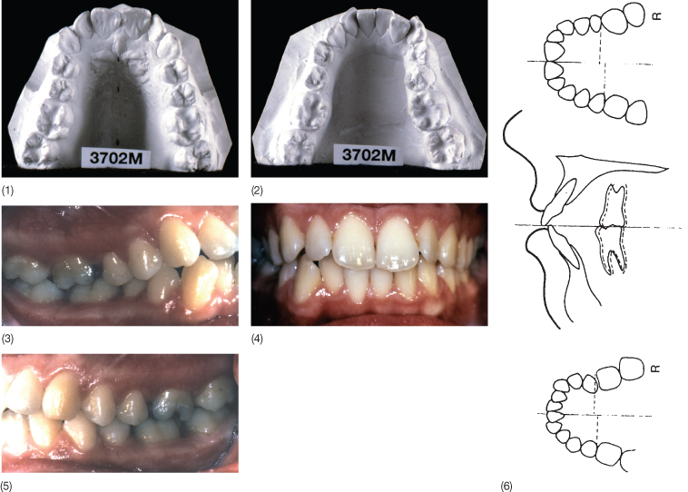
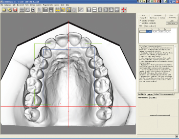
Fig. 5.9 Asymmetry in the position of the teeth in relation to the determined midline can be assessed on virtual models.
Once the midline has been determined on one of the two arches, it will be transferred to the other arch by superimposing the occlusograms on at least three occlusal contacts (Fig.
Stay updated, free dental videos. Join our Telegram channel
VIDEdental - Online dental courses


