Chapter 4
EXAMINATION
The initial examination has two primary objectives: To elicit sufficient data to make a correct diagnosis and plan of treatment and to make objective assessments which, wherever possible, should use scoring systems so that objective reassessment can be made; unfortunately, the objective scoring systems in dentistry are poor. Ideally, a sign should be 100% sensitive, 100% specific, 100% predictable and have 100% negative predictability. The sensitivity is the percentage of people (or in the case of periodontal disease, sites) who have the disease and also have the sign. Specificity is the percentage of people who do not have the disease and who do not have the sign.1 Predictability is the percentage of people (or sites) who have the sign and who will have the disease. Negative predictability is the percentage of people without the sign who will not have the disease.2 Ideally, therefore, everyone who has the disease would have the sign, everyone without the disease would not have the sign, everyone with the sign would progress to the disease and everyone without the sign would remain disease free. Unfortunately, none of the dental signs meet these criteria and the clinician must balance the relative diagnostic accuracy of the sign against the risk to the patient of not treating disease which is possibly present and the risk of treating when disease is possibly absent.
The following topics will be covered in this chapter:
- Charting systems
- Radiographic techniques
- Extraoral and intraoral examination
- Initial impressions, face bow and jaw registration, study casts
- Collation of data and initial diagnosis
- Initial communication with patient
- Special tests
Dentists who treat patients with failure in an extensively restored mouth have the unenviable task of carrying out a full mouth examination and diagnosis. They cannot concentrate solely on the periodontium, on the occlusion or on caries and, as such, must be up to date in all of the disciplines of restorative dentistry and have a standardized examination system covering every area. Very much like the pilot prior to take off, it is important that the dentist develops a standardized check list. The charting systems used must not be unwieldly. Combining charting systems from various specialist texts would be impractical. This chapter will describe an examination system which can be used routinely. Some aspects would only be included should the patient have related symptoms or signs. A comprehensive, careful, systematic examination technique is vital as diagnosis, treatment planning and treatment are totally dependent upon it.
The clinical significance of the findings of the examination will depend on:
- The extent of the restorative therapy required.
- The age of the patient. The 22 year old with restorative problems requires a different approach from the 70 year old with similar problems.
- The experience and ability of the dentist.
- The competence of the technical assistance.
- The social and physical environment in which both the dentist and the patient find themselves. What is appropriate therapy in one socio-economic environment may not be appropriate in another. Similarly, one dentist may have excellent technical support on the premises, whereas another may not have the availability of a suitably trained technician.
Charting Systems
Eight charts are used for the examination and are 30 mm x 21 mm in size (Greenbrook Dental Supplies Ltd.). (These could be complemented or replaced by computer records.)
Chart 1 (Page 34) collates the general information – the patient’s address, age, telephone numbers, referral, occupation, primary complaint and pertinent aspects of the history.
Chart 2 (Fig 3-1a, page 35) is a medical history questionnaire designed so that only marks in the “Yes” column are of relevance. Noteworthy aspects are highlighted by placing a red and/or allergy sticker on the outside of the patient’s folder, with an appropriate note (Fig 3-1c).
Chart 3 (Fig 3-1b, page 36) is the questionnaire used in relation to arthromyogenous pain.3 Positive responses in Questionnaire 1 are indicative of pain/discomfort. Positive responses in Questionnaire 2 are indicative of the local risks, that is, complicating dentistry. Positive responses in Questionnaire 3 are indicative of the level of dysfunction. Positive responses in Questionnaire 4 are indicative of the general risk factors and of a psychogenic aetiology.
Chart 4 (Fig 4-1a) consists of two parts. The top portion has space for findings of the extraoral, soft tissue and general occlusal examination. The lower portion is the caries/restoration chart.
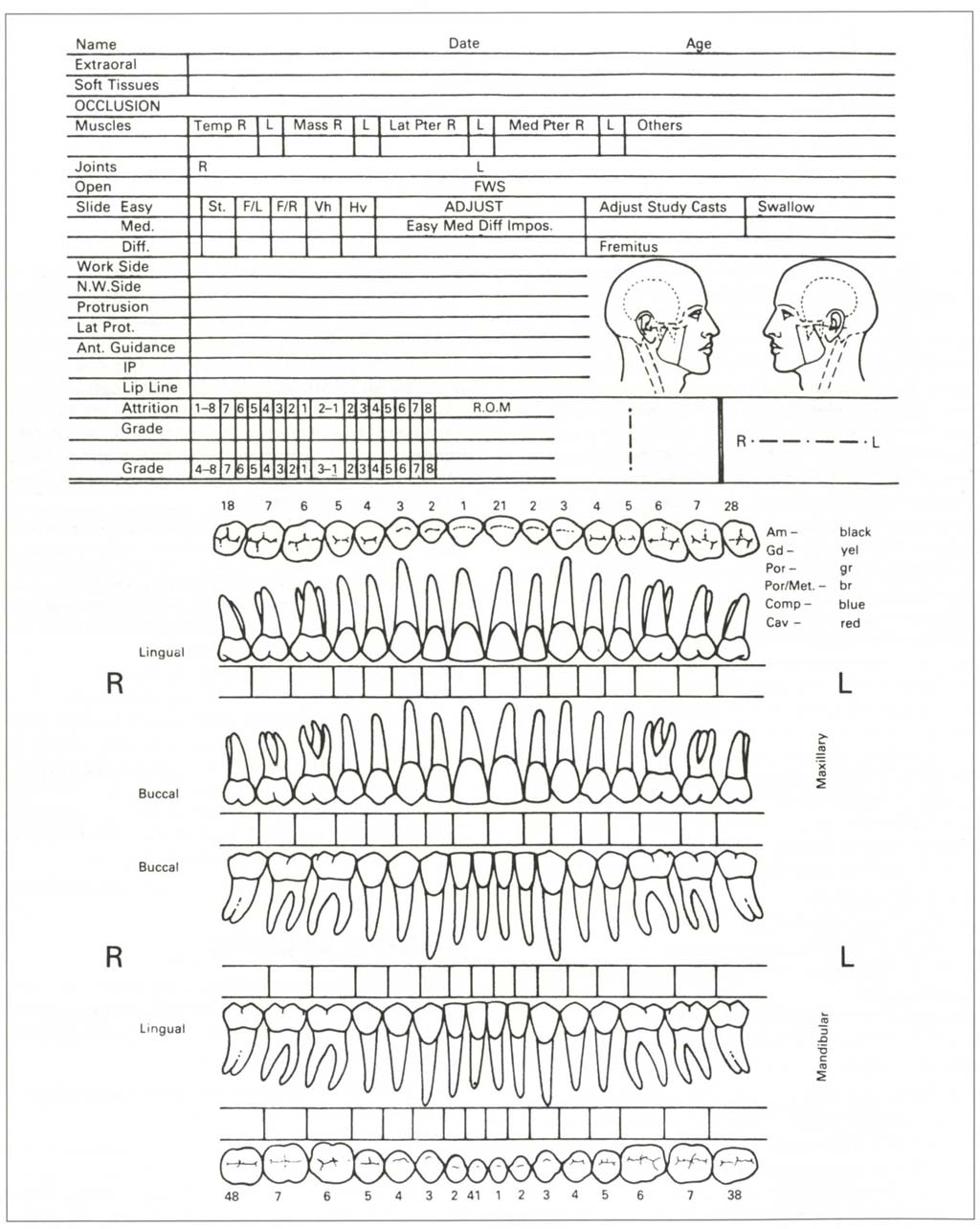
Fig. 4-1a Chart for extra-oral, soft tissue, occlusal and caries/restoration record.
Chart 5 (Fig 4-1d) is a combined periodontal and endodontic chart. Teeth are designated as follows: upper right quadrant is prefixed by 1, upper left prefixed by 2, lower left by 3, lower right by 4.
Chart 6 (Fig 4-1e) is used to record bleeding on probing.
Chart 7 (Fig 4-1f) is used to calculate the bleeding score.
Chart 8 (Fig 4-1g) is used to record soft tissue lesions.
Extraoral, Soft Tissues, Occlusion Chart
Figure 4-1b shows such a chart following the examination of a patient. An explanation of the chart headings is given below (headings in bold).
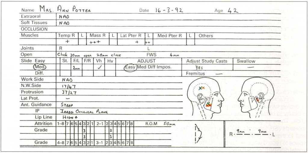
Fig. 4-1b Extra-oral, soft tissue and occlusion chart following examination of a patient. NAD = Nothing abnormal discovered. There were no extraoral or soft tissue abnormalities. There was some muscle sensitivity. The right masseter and temporalis muscles were more sensitive to palpation than the left. An opening and closing click from the right TMJ. A slide CRCP to IP that was slightly difficult to elicit with a 2 mm slide forwards and to the left with V/h. There was a deviation to the left on opening with 50 mm range of motion vertically and 9 mm to each side. N.W. side contacts between 17 and 47 and protrusive contacts between 37 and 27. Occlusal adjustment would be easy but adjustment of study casts required. Anterior guidance was steep with an irregular occlusal plane. High upper lip line. Grade three attrition (into dentine large cupped out areas) 13, 43, 23, 33. On diagram: Symptoms blue cross on face; response to palpation red; (X) – difference between muscle pairs – only uncomfortable; X – it hurts; XX – dramatic painful response; arrow – trigger area arrow site.
Extraoral and Soft Tissues. These relate to pathological lesions.
Muscle-sensitivity to palpation is graded as low to high, using o to + to +++ grading, from no sensitivity to severe sensitivity with eye reaction (see below). There is space for recording the results of palpation of the right and left Temporalis, Masseter, Lateral Pterygoid and Medial Pterygoid muscles. There is additional space for “Others” – being any of the remaining orofacial muscles which are sensitive to palpation.
Joints R L provides space to record clicking, crepitation and other relevant information for right and left joints.
Open records the ease of opening, or associated irregularities.
FWS records the interocclusal clearance in the rest position.
Slide refers to a discrepancy between the centric relation contact position and the intercuspal position and is circled as easy, medium or difficult, relating to the difficulty in obtaining centric relation and eliciting the slide. There is space to note whether it is straight forwards (St), forwards and to the left (F/L), forwards and to the right (F/R), plus the dimensions. There is space to record whether there is a large vertical : horizontal ratio (Vh), or a large horizontal : vertical ratio (Hv), and the associated dimensions and teeth involved.
Adjustment. There is space to note whether an adjustment of the occlusion appears to be easy, medium, difficult or impossible and whether or not study casts need to be mounted and adjusted.
Fremitus can be noted, as can the swallowing pattern.
Working side, non-working side, protrusive, latero-protrusive contacts can be entered.
Anterior guidance refers to comments about its presence or absence or irregularities in guidance.
Ip is the intercuspal position and allows entry of irregularities in this relationship.
Lip line during smiling, talking, grimacing, laughing is entered as maxillary high (meaning that maxillary gingival margins are exposed during one or all activities) or low (no gingivae exposed) and vice versa for the mandible. The location of marginal exposure is noted.
Speech. Any speech impediments are noted.
Attrition is graded as: 0 = no wear, 1 = shiny, flat enamel area not involving dentine, 2 = dentine exposed, 3 = gross loss of occlusal morphology.4
The Facial Profiles are used to record regions of the patient’s extraoral muscle symptoms (marked in blue) and response to palpation (marked in red) (X) = difference between muscle pairs but “only uncomfortable”; X = “it hurts”; XX = dramatic painful response; arrows are used to trace path from trigger area to reference area.5
ROM is Range of Movement. The vertical line is used to record the path of opening in the frontal plane, that is, to show displacements or deviations, the horizontal line is used to record lateral movements in the frontal plane. The dimensions of both are recorded.
Caries, Restorations Chart
The lower half of Chart 4 has diagrammatic representations of the occlusal, lingual and facial surfaces of upper and lower teeth with spaces below each tooth for comments. Coloured pencils are used for the charting (Fig 4-1c).
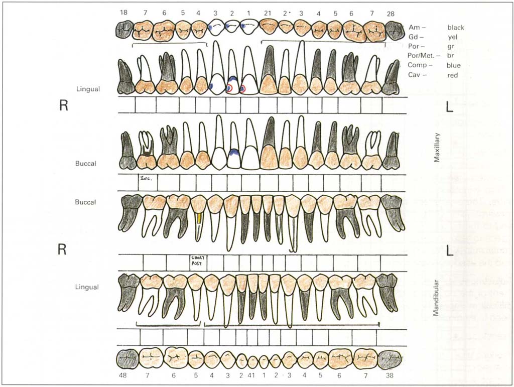
Fig. 4-1c Caries/restoration chart following examination. Missing teeth marked. Ceramometal bridge 17–14; 21–27; 37–44; 45–47. Short post in 45. Incomplete root filling 17. Composite restorations 13, 12, 11; 11 and 12 need replacing. 33 root filled. Am – amalgam; Gd – gold; Por – porcelain; Por/Met – ceramometal; Comp – composite resin, Cav – cavity.
Periodontal Chart
The left column (Fig 4-1d) denotes the tooth, the next six columns have spaces for pocket depth on the buccal and lingual surfaces at the mesial, middle and distal sites. Only depths greater than 3 mm are recorded, unless recession is present on that tooth, in which case crevice depth is measured so that total attachment loss can be calculated (see below).
The next two columns (CEJ) indicate the distance from the amelo-cemental junction to the gingival crest. The greatest distance is measured both buccally and lingually. Ideally recession would be measured at six sites for each tooth but this is neither practical nor necessary. There is then a wider space for furcations which are graded as:
(i) Horizontal loss of supporting tissues not exceeding one third of the buccolingual width of the tooth.
(ii) Horizontal loss of supporting tissues exceeding one third of the width of the tooth, but not encompassing the total buccolingual width of the furcation area. (That is, not through and through.)
(iii) Horizontal “through and through” destruction of the supporting tissue in the furcation.
Entries are Uppers: M = Mesio-buccal, D = Disto-buccal, P = Palatal. Lowers: M = Mesial, D = Distal, unless three or four rooted. Thus a Grade II furcation involvement between the mesio-buccal and palatal roots of an upper tooth would be M/P II.
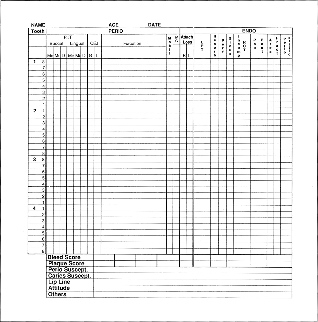
Fig. 4-1d (i) Combined periodontal and endodontic charting.
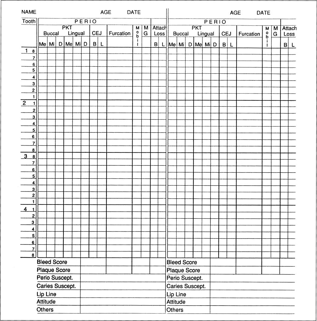
Fig. 4-1d (ii) Continuation periodontal chart for recall appointments.
Mobility is recorded6 in the next column as follows:
- Movement of the crown of the tooth, 0 to 1 mm in a horizontal direction.
- Movement of the crown of the tooth exceeding 1 mm horizontally.
- Movement of the crown axially, as well as horizontally.
In reality these gradings are:
- Slightly increased mobility.
- Moderately increased mobility.
- Markedly increased mobility (axial mobility).
The intermediate gradings of 1+ 2+ are frequently used.
MG denotes the presence of a muco-gingival involvement and this is denoted by +.
Attachment loss is noted for both the facial and lingual surfaces by adding pocket/crevice depth to the recession in the same line. The greatest loss of attachment is recorded for each surface. If a pocket is deeper than an adjacent pocket plus recession, then any recession associated with the deeper pocket is measured and added to that pocket to give attachment loss.
Plaque is scored subjectively as 0, 1, 2, 3. Number 1 indicates small amounts, 2 general plaque accumulation and 3 debris. This will be discussed subsequently, as will the headings, periodontal susceptibility and caries susceptibility.
Endodontic Chart
The Endodontic Chart (Fig 4-1d) has spaces to record electric pulp test (EPT) readings, resorption, presence of perforation, sinus, incomplete root filling, unsatisfactory post, peri-apical area of rarefaction or sclerosis, fracture, tenderness to percussion (periostitic).
At the base of the chart are spaces for bleeding score, plaque score, periodontal susceptibility assessment, caries susceptibility, lip line, patient attitude. Others allows entries to be made which are not accommodated elsewhere, such as the assessment of implants.
Bleeding On Probing Chart
Each tooth is represented by a square with a space for the buccal, mesial, distal and lingual portions (Fig 4-1e). Bleeding on probing is entered by placing a cross in the appropriate space. Percentage of surfaces bleeding can be calculated as described in Chart 7.
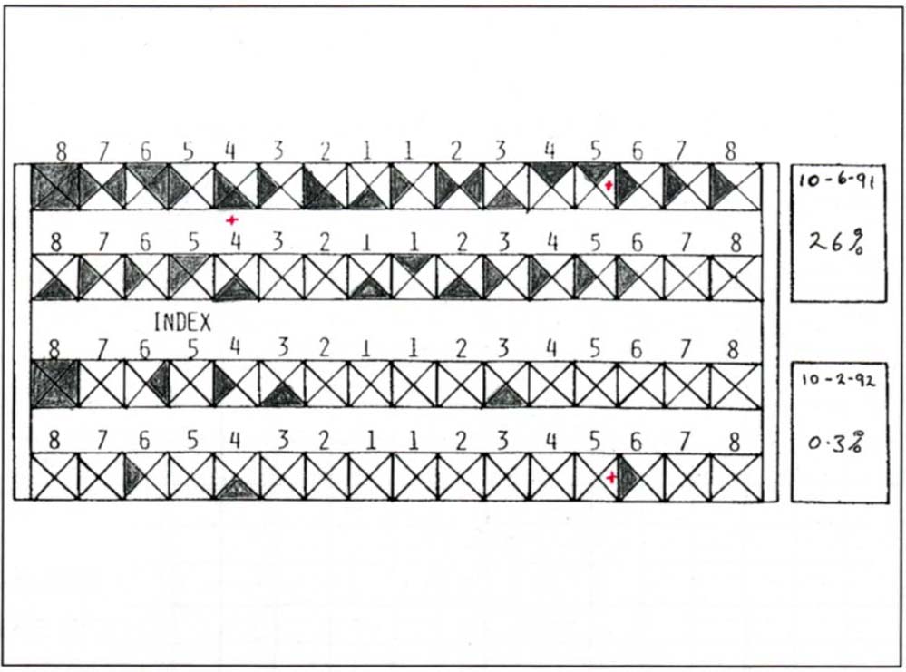
Fig. 4-1e Chart to record bleeding on probing. Bleeding on probing is entered by shading the appropriate space. The percentage of surfaces bleeding can be calculated from Chart 7 Figure 4-1f. A red X denotes purulent exudate.
Bleeding Score Chart
The total number of teeth is noted and the appropriate line found on the chart (Fig 4-1f). The number of surfaces bleeding is totalled and the horizontally opposite intersection, with the line denoting the number of teeth, gives the percentages that are bleeding. For example, 28 teeth with 56 bleeding units = 50% bleeding score. Thisfigure isthen entered atthe base of the periodontal chart.
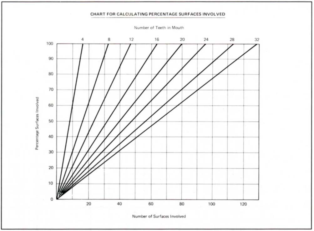
Fig. 4-1f Chart used to calculate the bleeding score. The total number of teeth is noted and the appropriate diagonal line found on the chart, for example, 20 teeth. The number of surfaces bleeding is totalled and a line projected to meet the diagonal line. A horizontal projection from the intersection gives the percentages that are bleeding. For example, 20 teeth with 40 bleeding surfaces equals a 50% bleeding score. This figure is then entered at the base of the periodontal chart.
Soft Tissue Chart
This chart (Fig 4-1g) is only included in the folder if such a lesion exists.
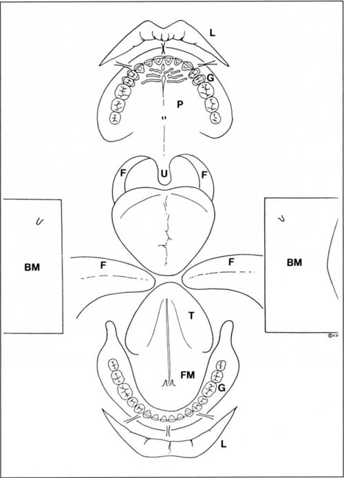
Fig. 4-1g Soft tissue lesion charting. The presence of a lesion is noted, dated and described on the chart. The chart diagrammatically represents: the lips L; palate P; fauces F; uvula U; tongue T; floor of mouth FM; buccal mucosa BM; gingivae G.
Chart Collation
Charts 2, 3, 4 and 5 are collated in a green card folder, 31 mm x 24 mm in size (Fig 5-1g). To make the findings easily accessible, the medical history is located on the outside and when the folder is opened, the occlusion, caries and periodontal/endodontic charts face the clinician. The periodontal/endodontic chart is only fixed along its top edge, so that it can be lifted to expose the bleeding chart. Similarly, Chart 8 can be included beneath the caries/occlusion chart. This format makes it easy for the chairside assistant to record the charting and is extremely convenient during planning. All charts are stored in a patient folder (Safeguard Systems).
Check List for Charting
- Do I have a good system for obtaining the medical history?
- Is my attention drawn to important aspects?
- Do I collect sufficient data about the occlusion?
- Can I readily differentiate between the types of restorations on my chart?
- Do I chart pocket depths?
- Do I chart attachment loss?
- Do I record the bleeding score?
- Do I chart mobility?
- Do I assess lip line?
- Do I have an endodontic assessment chart?
- Is my charting system unwieldly?
- Is my charting system adequate to collate the pertinent data?
- Can I open the chart on a desk and have all of the data clearly presented?
- Do I regularly reassess my charting system with my chairside assistant? my hygienist? my secretary?
Radiographic Technique
Dental Panoramic Tomogram
(ORTHOPANTOMOGRAM O.P.T) (Fig 4-2)
A panoramic survey provides a good general overview of the state of the dentition and the presence of radiographically identifiable pathosis. It also gives an indication of bone height available for implant placement and the location of vital structures. The vertical magnification is approximately 1.3x. The horizontal magnification varies around the arch.
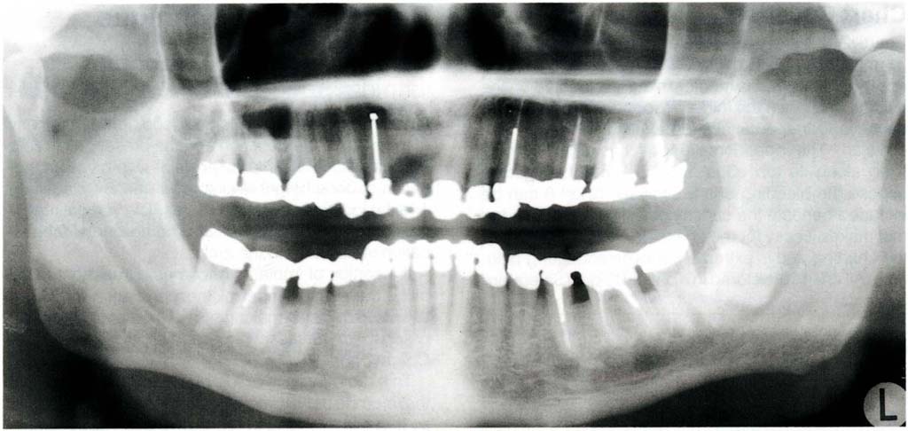
Fig. 4-2 Dental panoramic tomogram. This is a transpharyngeal projection with a limited focal trough – usually through the plane of the molar teeth. It cannot be used in restorative dentistry to assess joint space. Furthermore, the teeth are not in occlusion when the radiograph is taken.
If insertion of implants becomes a treatment possibility, then assessment of the panoramic tomogram assists in decision making, as to whether further radiographs are necessary for additional analysis (see Chapter 33).
This radiograph is made prior to the examination, if the referring dentists correspondence indicates a need so that it is available at the examination appointment, or following a very brief initial examination, to assess the need.
Full Mouth Periapical Radiographs
Long cone paralleling technique periapical and bitewing radiographs are made for all patients, using a 70 kv 10 milliamp X-ray machine with a DC head (SS White Intrex) with rectangular collimation and E speed film7 to obtain minimal distortion of images, good gradation of contrast and reduce exposure time. The sites to be radiographed are determined following assessment of the panoramic tomogram and initial examination. Usually, this will require a full mouth survey. The radiographs are mounted in a holder (Fig 4-3) (Ada Products Inc.). Radiographs are processed in an automatic developer and are available dry within four minutes. Long cone paralleling technique radiographs are taken to avoid the angulation errors of bisecting angle radiographs.8 Holders are used for the alignment (Rinn). For good penetration without too much greying 70 kv at 10 milliamps is used. A DC head is used to reduce radiation, by having a greater percentage of useful high energy X-rays and fewer non useful low energy X-rays.9
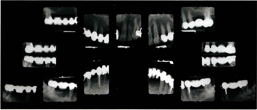
Fig. 4-3 Full mouth parallel beam long cone periapical and bite wing radiographs mounted in a holder which blocks out surrounding light (Adamount – 616B). Additional radiographs of teeth 47 and 37 with Gutta-percha points into the periodontal pockets.
Additional Radiographs
Radiographs for the examination of the TMJs and for the assessment of sites for the insertion of osseointegrated fixtures, are special tests and are considered on pages 112–115.
Check List for Radiography
- Has my X-ray machine been tested?
- Is it tested regularly?
- What is the kilovoltage and milliamperage?
- What film do I use?
- Is the tube collimated?
- Are my staff protected?
- Are my staff adequately trained?
- Are the rules for use clearly posted?
- Am I adequately trained?
- Have I registered with the appropriate regulating body?
- Do we wear monitoring badges?
- Do I use a lead apron for patients?
- Do I use the long cone paralleling technique?
- How controlled is my processing?
- Do I have a good viewing light?
- Do I have access to more specialized techniques?
- Am I careful only to prescribe radiographs when truly needed?
- Do I have to retake frequently, if so, should I change my technique?
- Am I able to interpret the radiographs that I have prescribed?
- If not, do I use the services of a specialist?
Examination Procedure
The aim is to develop scoring systems, so that disease pattern and dysfunction can be assessed objectively rather than subjectively in relation to the:
- Changing pattern of existing disease and/or dysfunction.
- Risk to the dentition and/or restorations of existing disease or dysfunction.
- Probability of the development of new disease or dysfunction and its associated risk.
Unfortunately, most of the available examination techniques are ill-suited to developing such systems.
During examination, attention is confined solely to observing and recording the current status, and treatment possibilities are not considered. Examination, diagnosis and treatment planning are separate entities.
The Sequence of Examination is:
1) Initial observation during history taking
2) Extraoral examination
Soft and hard tissues
Muscles
Joints
Speech
3) Intraoral examination
Soft tissues Muscles
Teeth and periodontium – general
assessment of the status
Initial radiographs
Occlusion
Periodontium
Teeth
Endodontic
Aesthetics
4) General
Speech
Attitude
Initial Observation
The examination starts whilst taking the history. The lip line is observed during talking and smiling for exposure of gingival margins. Any excessive facial muscle activity is noted.
Significance
High maxillary and low mandibular lip lines will create difficulties with aesthetics and marginal placement during crowning. Obvious muscle activity could denote bruxism.10
Extraoral Examination
The areas to be examined are the skin, the underlying soft and hard tissues, the muscles of mastication, the temporomandibular joints and speech. The patient should be placed in a semi-reclining position in the dental chair, with the head properly supported.
Skin
Check for any lesions, removing the patient’s spectacles to examine the butterfly area beneath the eyes for basal cell carcinoma.
Significance
In the presence of untreated pathosis, the failed restorative dentistry may be the least of the patient’s problems.
Underlying Hard and Soft Tissues
The underlying hard and soft tissues should be checked by palpation, feeling for any firm areas and enlargements. Sensitive areas and lymphadenopathies are noted.
Significance
As in the examination of the skin, in the presence of untreated pathosis, the failed restorative dentistry may be the least of the patient’s problems. Lymphadenopathy could signify an intraoral lesion.
Muscles
The temporalis and masseter muscles should be palpated (Fig 4-4a) in resting and clenched states. Pain may be elicited in otherwise symptomless muscles. A painful response is recorded on the occlusion chart. The muscles of the neck and scalp are also palpated. The medial pterygoid muscle is palpated at the insertion medial to the mandibular angle (Fig 4-4b).
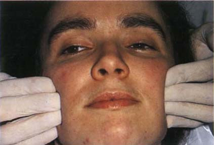
Fig. 4-4a Palpating the masseter muscle. This should be palpated both at rest and with the patient clenching the teeth. Similarly, the temporalis should be palpated.
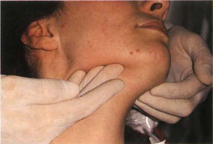
Fig. 4-4b Palpating the medial pterygoid muscle at the insertion medial to the mandibular angle.
Significance
Sensitivity to palpation should warn the practitioner against carrying out extensive restorative dentistry involving the occlusal surfaces, until such sensitivity has subsided either as a result of therapy or spontaneously in the natural cycle of such conditions. Muscle sensitivity indicates a high likelihood of non-reproducible jaw relationships which could lead to loss of control and predictability when restoring occlusal surfaces.
Temporomandibular Joint Examination
The fingertips are placed simultaneously over the lateral aspects of both joints. Slight medial pressure is applied to the joint and the patient is asked to report any symptoms. These are recorded in the same manner as are muscle symptoms. The patient opens and closes his mouth and any symptoms are recorded. The little finger is then placed in the external auditory meatus (Fig 4-4c) and pushed anteriorly to detect symptoms originating in the posterior and lateral aspect of the joint, both at rest and with opening and closing the mouth. Clicks and crepitus can usually be elicited and the opening or closing interincisal measurement at which they occur is recorded. The patient is asked to open his mouth. Deviations, the shift of the jaw midline during opening that disappears with continued opening (that is, a return to the midline) or deflections, the shift of the midline to one side that becomes greater with opening and does not disappear at maximum opening (that is, it does not return to the midline)11 are noted and drawn on the ROM section of the occlusion chart (Fig 4-1b). The patient is requested to open as widely as posible on two or three occasions. The maximal interincisal distance at opening is measured, as are left and right lateral excursions. Clicks can be further investigated by listening with a stethoscope or by using ultrasound equipment (Doppler – Denar Instruments). The latter can give more information regarding the nature of a meniscal lesion, although I have not found the need for such instrumentation and Mohl et al. questioned, in 1990, the efficacy of ultrasound.12
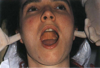
Fig. 4-4c Palpating the temporomandibular joints, fingers in the ears. Deviation – shift of the jaw midline during opening that disappears with continued opening. Deflection – shift of midline to one side that becomes greater with opening and does not disappear on maximum opening.
Significance
Dworkin in a critical appraisal of research diagnostic criteria, in 1992,13 clearly highlights the inadequacies of current criteria and the conclusions drawn from them. The clinical findings act as a guide to management but their significance must be subject to constant review.
Clicking: This may have been treated unsuccessfully by extensive restoration of the dentition to an anteriorly positioned mandibulo-maxillary relationship. The efficacy of such treatment is not substantiated by well controlled clinical research. Whereas most clicks do not require treatment other than reassurance of the patient, those that do should be resolved prior to restoration. This is considered further in Chapter 28.
Consequences of Clicking
(i) No progression (this is the most common outcome). There may be morphological changes in the joint, but these do not give rise to complaints or changes in the symptoms.
(ii) Progressive degeneration of the meniscus, leading to pain, with increasing restriction of movement and locking.
There is no conclusive evidence regarding the natural history of the clicking joint.14 This will be considered further in Chapter 28.
Deviation: during opening movements, this probably indicates a meniscal interference in one or both joints, whereas a deflection results from restricted movement in one joint and would usually be caused by muscular disharmony, but could also be due to meniscal interference disorders.
Restricted mandibular opening: this is defined as less than 40 mm and indicates the need for caution in restorative therapy (normal opening – 55 mm male, 50 mm female).15 Restricted excursions are defined as less than 9 mm.
According to Lundh et al. in 198716, clicking with lateral joint tenderness, missing molars, localized abrasion and pain on chewing, is more likely to be followed by locking than clicking is when such signs do not present themselves.
Differentiation between Myalgia and Arthralgia of Intracapsular Origin
If the patient presents with a history of functional facial pain (that is, pain during chewing), there is sometimes difficulty in diagnosing whether this emanates from the muscles or from within the joint (intracapsular). The following six tests may then be of value:17
Translation – Smoothness of movement (Fig 4-5a, p. 56) The mandible is clasped between the thumb, which is placed on the occlusal surface of the molar teeth and the first finger, which is placed beneath the lower border of the mandible. The patient is then directed to translate: muscle problem – smooth movement, joint problem – rough movement.
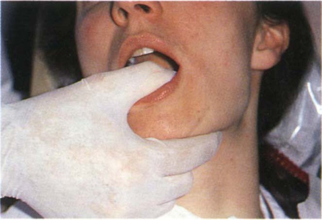
Fig. 4-5a Testing for smoothness of movement during translation. Muscle problem – smooth movement, joint problem – rough movement.
Endfeel (Fig 4-5b)
Instruct the patient to open as wide as possible, then try and increase the opening by pushing down on the incisal edges of the mandibular incisors. Muscle problem – some elasticity is felt, joint problem – rigid endfeel.
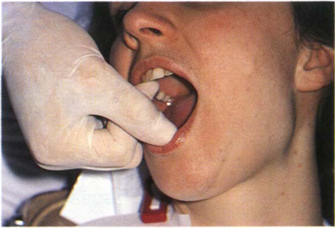
Fig. 4-5b End feel. Muscle problem – some elasticity, joint problem – rigid end feel.
Dynamic Opening (Fig 4-5c)
An upward force is applied to the chin by the clinician and the patient opens against resistance. Muscle problem – pain, joint problem – pain. This confirms the functional nature of the symptoms, but does not differentiate between muscle and joint pain.
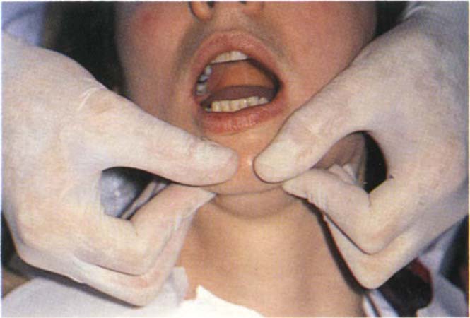
Fig. 4-5c Dynamic opening. Opening against resistance. The fingers push upwards and the patient opens. Muscle problem – pain; joint problem – pain.
Static Opening (Fig 4-5d)
Prevent the movement of the mandible by upward force and instruct the patient to try and open the mouth – no movement must be allowed. Muscle problem – pain, joint problem – no pain.
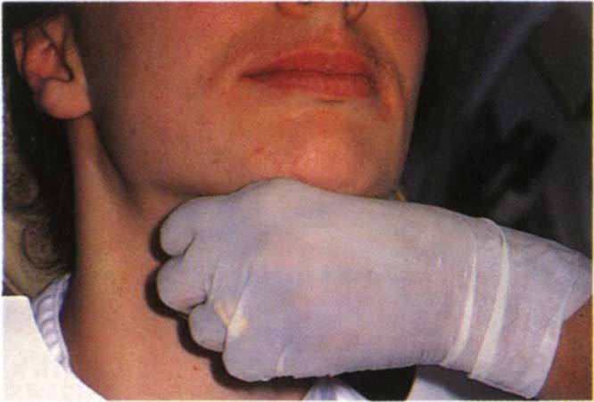
Fig. 4-5d Static opening. Instruct the patient to open the mouth, but prevent the movement of the mandible by upward force. Muscle problem – pain; joint problem – no pain.
Joint Detraction – Biting on a separator (Fig 4-5e)
Muscle problem – pain elicited on that side unless only the inferior lateral pterygoid muscle is involved. Joint problem – no pain, or reduction in existing pain.
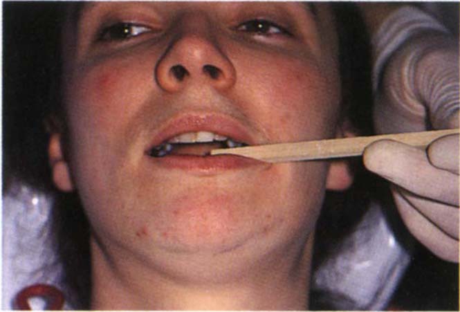
Fig. 4-5e Joint detraction. The patient bites on the separator. Muscle problem – pain on that side unless the inferior lateral pterygoid muscle is involved; joint problem – no pain or reduction of existing pain.
Protrusion Against Resistance with Separator in Place (Fig 4-5f)
Problem in inferior lateral pterygoid muscle – pain, joint problem – no pain.
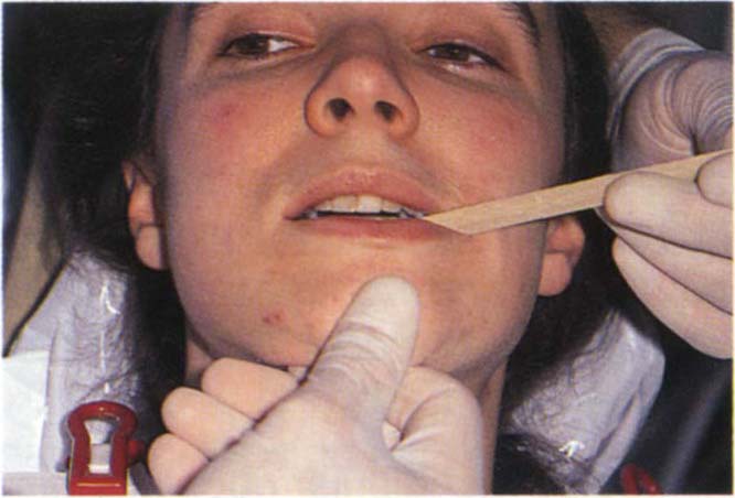
Fig. 4-5f Protrusion against resistance with separator. Inferior lateral pterygoid muscle problem – pain; joint problem – no pain.
The findings of these tests can be summarized as follows:
| Muscle | Intracapsular | |
| Translation Endfeel Dynamic Pain Static Pain Joint Detraction Protrusion/Resistance |
smooth elastic yes yes pain pain |
rough stiff yes no relief no |
It was reported in 1989 by Bezuur et al.17 that patients with myogenous pain generally have bilateral pain, whereas those with intracapsular pain are more likely to have unilateral clicking and unilateral dynamic pain. Those with pain of psychogenic origin are more likely to have less dynamic pain than the joint pain group and more static pain than the myogenous group.
Significance
Diagnosis is necessary before appropriate therapy can be instituted. Failure of conservative therapy to reduce intracapsular symptoms to a tolerable level may indicate the need for arthrography, tomography, magnetic resonance imaging and arthroscopic investigation. Differentiation must be made between a painful internal derangement which is free from stress related features and that which may be secondary to facial arthromyalgia of psychogenic aetiology. Further conditions to be considered in differential diagnosis are the arthroses, arthritis, external and middle ear and parotid disease and rarely nasopharyngeal tumors which can give rise to referred pain and dysfunction, but usually with some degree of sensory impairment.18 Myogenous symptoms are usually managed using conservative methods (see Chapter 26).
Speech
The patient’s speech is assessed. Any impediments are noted. If impediments are severe, and/or if the patient complains about his speech following previous restoration, it is sensible to make an audio recording of the speech prior to re-restoration.
Significance
Speech problems may be corrected by alterating the contours of the restorations and embrasures. It is important to record any existing impediments, so that any re-restoration cannot be indicted at a later stage.
Intraoral Examination
This includes soft tissues, muscles, teeth, periodontium and occlusal relationships, together with radiographic examination.
A preliminary examination of the patient’s primary complaint should be made at this stage, but it is important not to dwell unduly on this aspect. A systematic full mouth examination must be carried out without becoming side-tracked in long discussions about the primary complaint.
Soft Tissues
The intraoral examination should commence with each of the soft tissues. The mucosa is observed. The cheek and floor of the mouth are palpated bi-manually (Fig 4-6) and the tongue is examined by clasping it in a gauze square and moving it gently forwards and to each side to examine the posterior lateral borders.
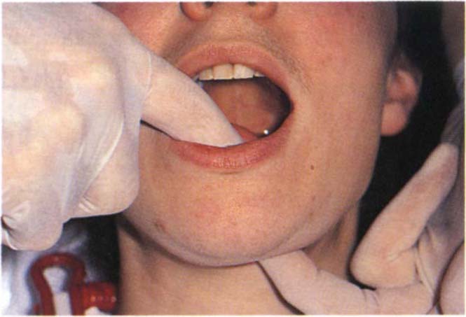
Fig. 4-6 Bimanual palpation of the floor of the mouth.
Significance
Restorative therapy may take a completely different direction/form in the presence of more ominous pathosis.
Muscles
Muscles are examined on each side: Lateral pterygoid and temporalis insertion.
Lateral Pterygoid
The patient is asked to open slightly and move the jaw toward the side to be examined. The index finger then slides along the anterior ramus of the mandible and behind the tuberosity (Fig 4-7). Lateral pterygoid tenderness is typically demonstrated by the patient screwing up the eyes with discomfort, or moving his head away from the examining finger. It is important that the fingernail is cut short and only gentle but firm pressure applied. Johnstone and Templeton suggested in 198019 that sensitivity is due to the stimulation of a trigger area associated with the insertion of the temporalis muscle and does not arise from the lateral pterygoid muscle, although this is disputed by Solberg in 19863. In 1989 Zijun et al.20 reported that palpation is not a reliable method of testing lateral pterygoid muscle dysfunction. However, tenderness to palpation in this area is of clinical relevance and should caution the clinician against rapid interference with the occlusion.
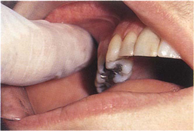
Fig. 4-7a Palpating the area of insertion of the lateral pterygoid muscle behind the tuberosity (see page 57 regarding the possibility of palpating the lateral pterygoid muscle).
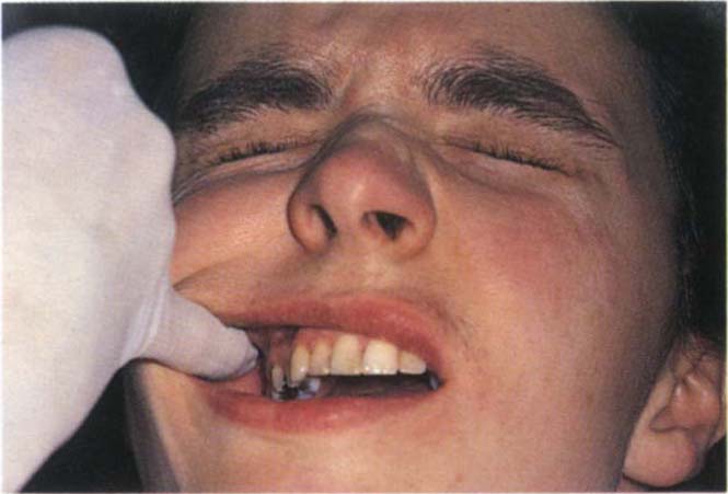
Fig. 4-7b Typical response of closing the eyes tightly if the palpation is sensitive.
Insertion of Temporalis
This is palpated on the anterior border of the ascending ramus, tenderness may be elicited.
For a more detailed examination of the muscles and joints the reader should refer to Okeson, 1985b21. However, the tests outlined above are sufficient for most cases.
Significance
Muscular and joint pain cannot be eliminated by re-restoring a dentition. The symptoms and signs must be removed by appropriate therapy prior to provision of definitive restorations. The presence of muscular dysfunction and/or joint pain increases the difficulty of providing extensive re-restoration in a controlled and predictable manner. Alteration of the occlusion in the presence of muscle symptoms can result in unexpected alterations in mandibulo-maxillary relationships which can occur, for example, between the jaw registration stage and the fitting of restorations.
Teeth and Periodontium – Initial Assessment
The panoramic tomogram is examined and a brief intraoral assessment made without any instrumentation to gain some idea of the status of the teeth and supporting structures. Periapical and bite wing radiographs are then taken. These are processed and mounted so as to be ready for viewing at the conclusion of the examination.
Occlusion
Probing of pockets and teeth can give rise to sensitivity which then makes it more difficult to manipulate the mandible. It is better, therefore, to carry out the occlusal examination next, before periodontal probing.
The following points should be observed when carrying out the occlusal examination: the intercuspal position, centric relation contact position, the movement between centric relation contact position and the intercuspal position – “slide in occlusion”, lateral contact positions and excursions, protrusive contact positions, excursions and guidance, the rest position and the vertical dimension. It is important for the practioner to know where to look and what to look for.
Significance
Seligman and Pullinger concluded from a thorough review of the literature in 199122 that no well controlled studies have been published which implicate the occlusion as an aetiological factor in TMD (page 388). The situation is similar for human studies which investigate the relationship between occlusion and periodontitis (pages 225 and 230).
The primary reasons for advocating in this text, that the dentist pays attention to the occlusion, are considered in Chapter 10 and are summarized as:
- To reduce mobility if caused by the occlusion.
- Patient comfort.
- Mechanical integrity of restorations, teeth and osseointegrated fixtures.
- To maintain control so that treatment can progress in a predictable manner.
The Intercuspal Position (IP)
This is the relationship of the mandible to the maxilla when the teeth are meshed maximally together (Fig 4-8a).
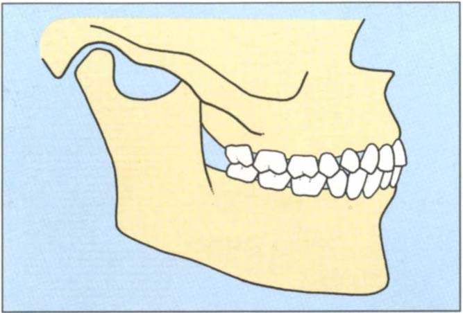
Fig. 4-8a The intercuspal position is the relationship of the mandible to the maxilla when the teeth are meshed maximally together.
Location
The patient is asked to bring his teeth together in the position of “best fit”.
Observation
The overall arch relationships are noted, recording details of irregularities such as crossbite and overerupted teeth. Horizontal overjet and overbite should be measured and recorded, especially noting if the upper and lower incisors and canines contact.
Significance
Function: the occlusion may be functionally unacceptable, usually as a result of tooth loss and over-eruption. Alteration by means of tooth reshaping or restoration may be necessary. However, malaligned teeth in the intercuspal position may be functionally acceptable.
Aesthetics: Figure 4-8b shows a patient whose acquired intercuspal position was aesthetically and functionally unacceptable to him.
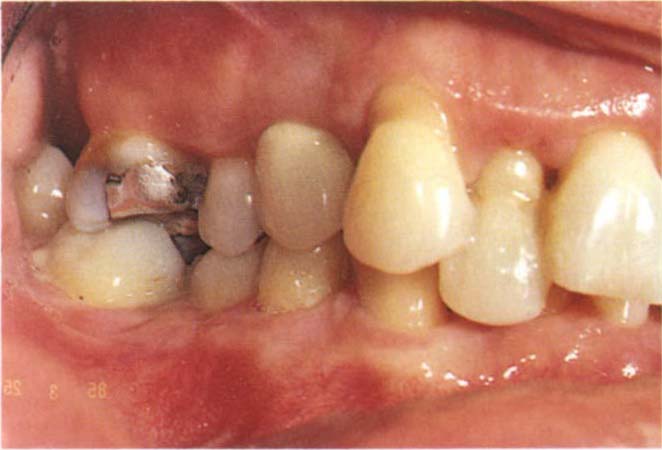
Fig. 4-8b The acquired intercuspal position was aesthetically and functionally unacceptable to the patient – due to food packing between 35 and 36 and trauma to the palatal gingiva of 22 from 32.
Traumatic relationships: these may occur between a tooth and the opposing soft tissue, and can sometimes be alleviated by adjustment of the intercuspal position. It can also occur between opposing teeth, resulting in either wear, or mobility, and/or drifting or mechanical failures. The alteration of the intercuspal position by occlusal adjustment, restoration or orthodontics may result in a more acceptable tooth relationship.
Adaptation to wear: although eruption may occur, together with attrition, the resulting relationships in the intercuspal position may prevent the dentist providing satisfactory restorations because of inadequate crown height (Fig 4-8c). Sometimes the position requires modification by small increases in vertical dimension to provide room for placement of the restorative material. This must be done with caution and only following a trial period of temporary restorations. It may be combined with clinical crown lengthening procedures, as described in Chapter 20 or intrusion of the lower incisors, described in Chapter 24.
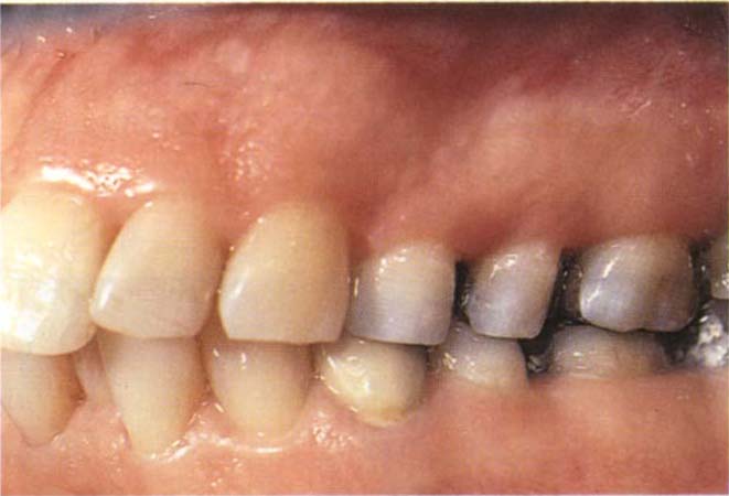
Fig. 4-8c Short clinical crown height (mandibular teeth) in the intercuspal position prevents the provision of satisfactory restoration in this position, unless clinical crown lengthening surgery is carried out. Alternatively, the maxillary teeth could be shortened, but this would compromise the aesthetics and the pulps. Alternatively, the vertical dimension must be increased to provide room for the restorative material. This alters the IP and brings the incisors out of contact, thus complicating treatment.
Intercuspal position acceptable: if restorations are required and the dentist decides that the intercuspal position is acceptable, he must ensure that the restorations reproduce the existing position accurately. Alterations in IP should be prescribed and planned and not haphazard. See Chapters 11 and 12.
Centric Relation Contact Position (CRCP)
The relationship of the mandible to the maxilla, in which initial occlusal contact has occurred following closure with the condyles in their most superior position in the fossae, with their anterior surfaces functioning against the posterior facing surface of the eminentia (Fig 4-8d).23 This position is clinically discernable when the mandible is directed superiorly and anteriorly and restricted to a purely rotary movement about a transverse horizontal axis.24
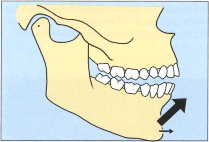
Fig. 4-8d Centric relation contact position. The relationship of the mandible to the maxilla in which initial occlusal contact has occurred following closure with the condyles in their most superior position in the fossae with their anterior surfaces functioning against the posterior facing surfaces of the eminentia. If the teeth are “squeezed” together, the incisal plane action of the cuspal inclines forces the mandible upwards and forwards into the intercuspal position.
Location
Slight modifications in technique may be necessary to suit individual needs. Patients differ in the relative ease of location of this position.
Technique for “easy patient”. The patient is placed in a reclining position in the dental chair and made as relaxed as possible. The head is cradled between the operator’s chest and arm to offer stability. The patient should be spoken to calmly and confidently. The thumbs are placed on the chin while the fingers support the body of the mandible (Figs 4-9a, b). With slight downward pressure from the thumbs and upward pressure from the fingers, the mandible is gently oscillated to a position just short of occlusal contacts. When the patient is felt to be relaxed, closure is then continued under the control of the operator until initial contact is felt by the patient who is asked to identify the area of such contacts. Shaking the mandible violently does nothing more than frighten the patient with resultant “tightening of the muscles” which is contrary to what is required.
Fig. 4-9 Jaw manipulation technique for the ‘easy patient’. It is essential that the patient feels secure and that manipulation is carried out in a calm and relaxed atmosphere. The patient is supine.
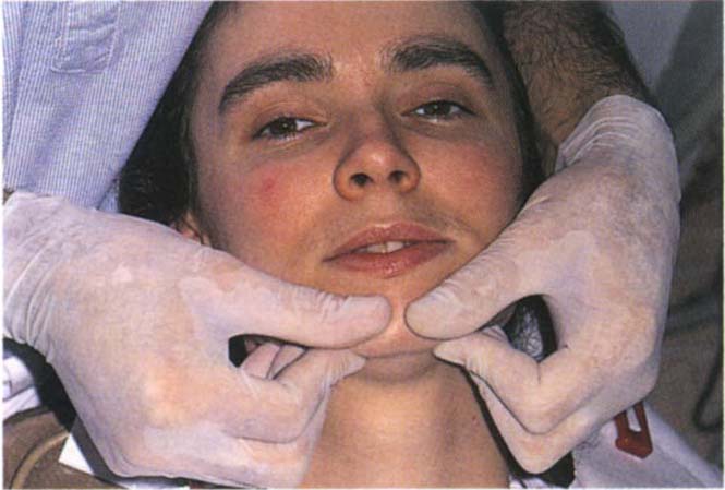
Fig. 4-9a The fingers support the body of the mandible, the thumbs are placed on the chin each side of midline. The head is cradled by the operator for support. The thumbs press gently downwards whilst the fingers support the body of the mandible. It is important that the fingers do not press on soft tissues medial to the lower border of the mandible since any perceived obstruction of the airway will result in a protrusive movement to protect the airway.
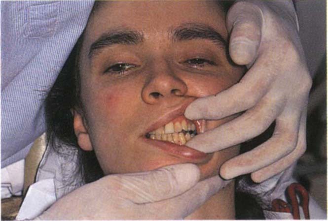
Fig. 4-9b Single handed manipulation. The thumb is placed horizontally across the chin, the first finger is extended to support one side of the mandible and the middle finger curled backwards to support the other side. Ensure that the lower lip does not become trapped between the thumb and the upper incisors. Also ensure that the chin is not squeezed between the thumb and the hand. The non-manipulating hand is free to separate the lips.
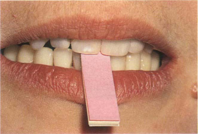
Fig. 4-9c Leaf gauge between the incisors to separate the posterior teeth and encourage superior positioning of the condyles. The paper leaves can be removed one by one to produce the minimal opening without tooth contact.
If difficulty is obtained in relaxing the patient, the first thing to do is to look at yourself to be sure that you are in fact relaxed and calm and reassuring the patient.
Ensure that the fingers supporting the mandible do not press into the soft tissues of the neck. Any perceived obstruction to the airway will elicit contraction of the lateral pterygoids to protect the airway, with resultant protrusion.
Patients who present slight difficulty in manipulation of the mandible. It is sometimes helpful to use a simple anterior stop to prevent tooth to tooth contact. A tongue spatula is placed between the upper and lower incisors and the patient asked to close on it. This position is maintained for approximately five minutes so as to “break up” proprioceptive reflexes and enable the patient to “forget” the habitual position of the mandible. The mandible is then manipulated, as described previously, to close against the tongue spatula. Finally, the spatula is slowly removed and the patient’s jaw closed to initial contact, as before.
Alternatively, a leaf gauge of thin mylar or paper strips is inserted between the teeth and the strips slowly removed until tooth contact occurs (Fig 4-9c).25 Sometimes it is advisable to place the gauge between the teeth and have the patient wait for half an hour in the waiting-room.
Patients who present more difficulty in manipulation. It may be necessary to make some form of occlusal stabilization appliance (Figs 4-43b, c, page 108), which is adjusted periodically until the mandible can be manipulated easily.
Observation
The teeth in contact, the area of contact, horizontal and vertical overjet and ease of manipulation are all points which should be noted.
Movement from Centric Relation Contact Position – To Intercuspal Position
Location
Manipulate the mandible to the CRCP and then instruct the patient to squeeze the teeth together until a position of “best fit” is reached.
Observation
Examine the incisors to determine the:
Direction, that is, whether the slide is straight forwards, forwards to one side, sideways only.
The vertical and horizontal dimensions of the slide. This is the distance travelled by the lower incisors in the vertical and horizontal planes. Figures 4-10a, b, e, f, show a large vertical component and a small horizontal component at the incisal region. Compare this with Figures 4-10c, d, g, h which show a small vertical and large horizontal component.
Fig. 4-10a+b Diagrammatic representation of large vertical : horizontal ratio between CRCP and IP.
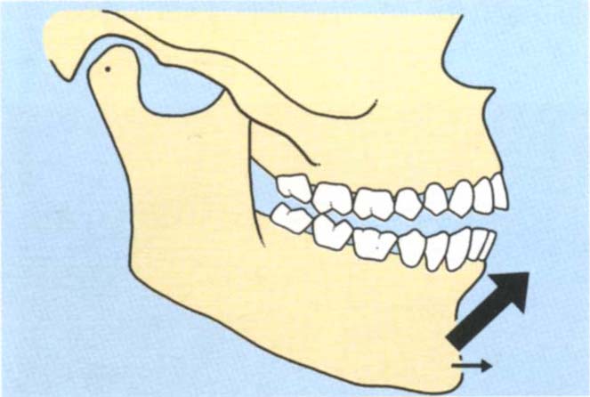
Fig. (a) CRCP
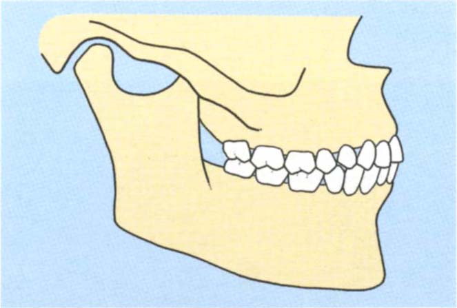
Fig. (b) IP
Fig. 4-10c+d Diagrammatic representation of a large horizontal : vertical ratio between CRCP and IP.
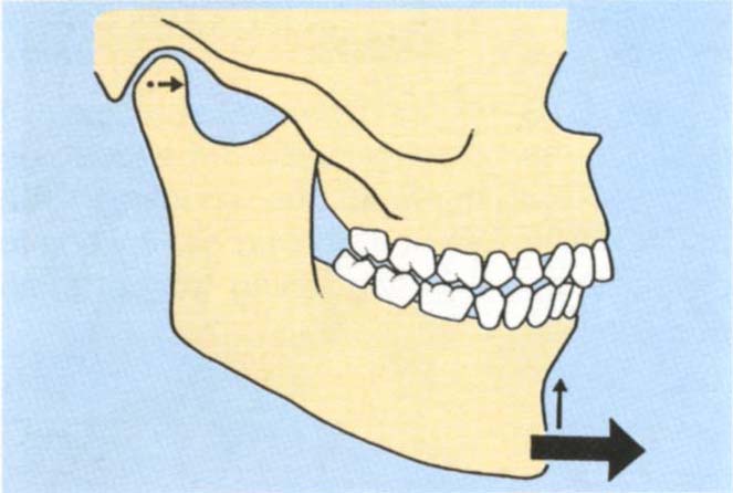
Fig. (c) CRCP
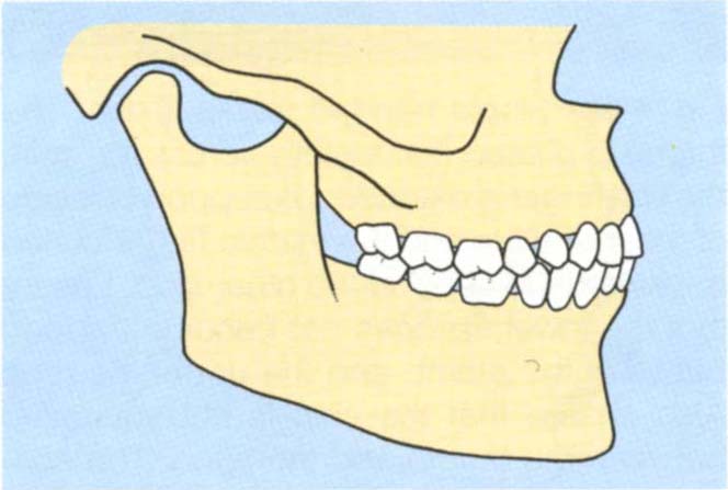
Fig. (d) IP
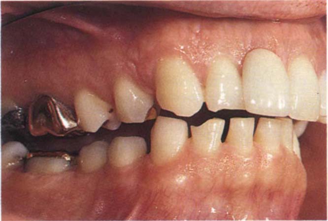
Fig. 4-10e CRCP
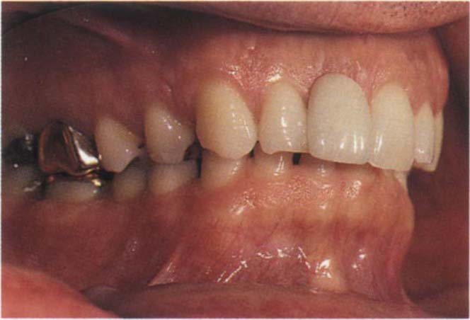
Fig. 4-10f The IP in a patient with a large vertical : horizontal ratio between the two positions. Note that in CRCP there is a large vertical separation between the anterior teeth.
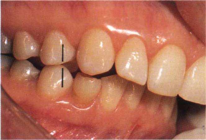
Fig. 4-10g CRCP
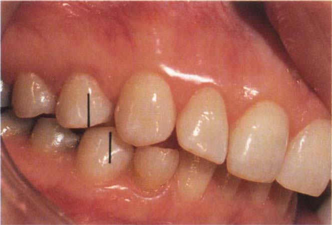
Fig. 4-10h The IP in a patient with a large horizontal : vertical ratio between the two positions. Note that there is very little vertical separation between the anterior teeth in CRCP. Tooth 44 has moved forwards approximately one half unit from CRCP, as shown by the vertical lines. The movement is primarily horizontal with very little vertical component. In CRCP the incisors do not contact. In IP they contact.
Vertical: horizontal ratio of the slide. This is the vertical dimension divided by the horizontal dimension. According to whether the vertical or horizontal component is greater, it may be more or less than unity.26
Horizontal: vertical ratio of the slide is the horizontal dimension divided by the vertical dimension.
Methods of determining the vertical : horizontal ratio of the slide:
1) Observe the movement at the tips of the lower incisors and estimate which is the greater – the vertical or horizontal movement. This is difficult to do, but prior practice with mounted casts as described in number 4 enables a valid clinical assessment to be made.
2) Guide the patient to CRCP and place a ruler or periodontal probe horizontally against the incisal edge of the embrasure, between the upper central incisors and the lower incisors. Mark with a wax pencil the point of contact on the lower incisor. Replace the ruler or probe to touch the mark. Ask the patient to squeeze the teeth together until they fit well (first practice the movement). The probe or ruler will be pushed anteriorly. Read the horizontal distance moved directly from the probe or ruler. Remark the contact position of the probe or ruler tip on the lower incisor. Measure the distance between this and the first mark. This represents the vertical component. Divide the vertical component by the horizontal component.
This method is not very accurate. The vertical component in particular is difficult to determine. However, the results offer an acceptable clinical guide.
3) Jaw movement measuring devices. Instrumentation such as the Sirognathograph (Siemans Co.) and Saphon Visi Trainer (Tokyo Shizaisha Co. Ltd.) may, with future modification, enable the vertical and horizontal components to be measured directly from tracings of the movement of the incisal point. A microcomputer interface would enable the ratio to be computed rapidly. If this instrumentation becomes economic in both purchase price and time, the information obtained will be very valuable.
4) Measurement from mounted casts. (This is a special test, but for convenience will be described here.) The mounting of casts in CRCP is described in Chapter 14 and in the Appendix.
Assessment can be made from the mounted casts, as in the mouth. Alternatively a more accurate assessment can be made by first, modifying a local anaesthetic needle to fit onto the end of the incisal pin (Fig 4-11a). The needle is first shortened to 1 mm. The incisal pin is coated with Vaseline and DuraLay resin added around the needle and over the pin, to make the needle into a removable extension of the pin. A piece of pressure sensitive paper (electrocardiogram paper or Denar tracing paper) is placed on a flat incisal table. The casts are positioned in the CRCP and the incisal pin lowered so as to contact the paper on the table. It is imperative that the pin adjustment screw is slightly loosened and the pin held firmly against the upper member of the articulator (Fig 4-11b). If the pin is not held as described, it will “wobble” in its housing, leading to inaccurate marking. The position of the pin on the vertical scale is recorded. The pin is lifted from the paper and the casts moved into the IP. The pin is held as before and is lowered into contact with the paper and the vertical position recorded. The paper will mark on both occasions. If the horizontal movement is only in the saggital plane, the distance between the two marks can be measured to give the horizontal movement. If there is also a lateral component, then lines are drawn through the pin marks, perpendiculartothe saggital plane (Fig 4-11c) and the shortest distance between the lines measured. The vertical component of the slide can be calculated from the two vertical recordings, the horizontal component from the paper marks. The curved incisal pin housing present on some articulators (such as Denar articulators) removes the error due to projection effects occuring at the tip of the pin when changes are made in the vertical dimension – as with closing from CRCP to IP. The ratio is calculated.
Fig. 4-11 Measurement of the vertical : horizontal ratio of the slide from CRCP to IP.
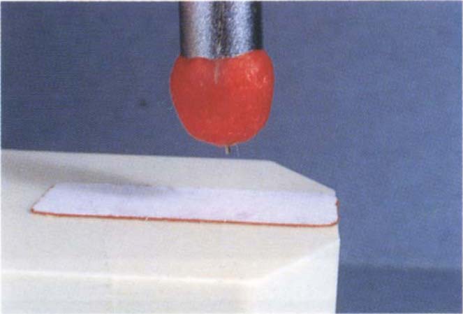
Fig. 4-11a Modified incisal pin. 1 mm of local anaesthetic needle extends from a DuraLay cap.
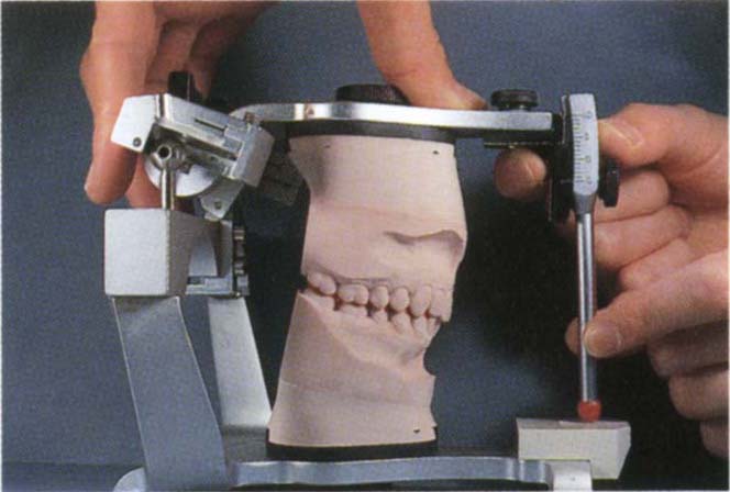
Fig. 4-11b Incisal pin held firmly and lowered to pressure sensitive paper placed on the incisal table.
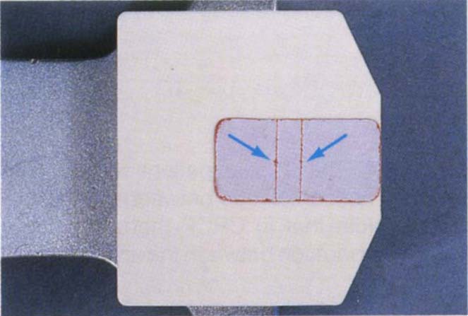
Fig. 4-11c Horizontal lines on pressure sensitive paper. Note the two needle marks.
When practising these assessments, it is best to make measurements on mounted casts. At a later stage it is possible to assess most cases directly in the mouth, without measurement. Some cases have a very obvious ratio, whereas others are more difficult to assess.
Significance
Bruxism. This is the grinding or gnashing of the teeth, usually during sleep. Both, Ramfjord in 196127 and Dawson in 197428, consider that adjustment of the teeth to achieve even, occlusal contacts in centric relation, together with elimination of the slide from CRCP to IP, will eliminate bruxism. Well-controlled clinical studies are required to substantiate this claim before occlusal adjustment can be advocated for the elimination of bruxism (see page 209). Seligman and Pullinger concluded from a thorough review of the literature in 1991,22 that “parafunction approaches universality and that past research failed to show any lasting harmful effects of bruxism in healthy individuals”. Bruxism often occurs during the rapid eye movement of sleep and if primarily a clenching activity may not produce sounds. Further, it may fluctuate from one day to the next.29 As such, any study of bruxism must record both muscle activity and sound at night over a prolonged period. The patient’s subjective response to questioning is not reliable evidence.
It should be realized, however, that alteration of occlusal form can alter the pattern of existing bruxist activity. For example, if a patient were bruxing on the upper first molar and this tooth were extracted, bruxism would occur elsewhere. With careful management of the occlusion, the dentist is able to direct the very heavy loads generated during bruxism through those teeth and restorations best suited to receive such loads.
Adaptation. The intercuspal position is an adaptive mandibulo-maxillary relationship, deflective contacts in centric relation may lead to a path of closure which avoids the “single tooth contacts”, that is, the intercuspal position may depend upon avoidance of centric relation contacts. Fig 4-12 shows the important difference between centric relation contacts and contact in the intercuspal position.
Consider a tooth which is to be restored and is an initial contact in centric relation. Elimination of the occlusal surface during tooth preparation will remove the deflective contact and may result in an alteration of the intercuspal position, there no longer being any need to avoid the deflective centric relation contact. There is, however, insufficient experimental data to allow the clinician to determine, with confidence, when such an alteration will occur.
The first possibility to be considered is that the tooth or teeth to be prepared are not initial contacts in centric relation (Figs 4-12a, b, c). Consequently, clearance between the prepared occlusal surface and the opposing teeth can be predicted: thus, if 1 mm of occlusal tissue is removed, 1 mm of clearance results (Fig 4-12c).
Fig. 4-12 Diagrams to illustrate several possibilities when crown preparations are made.
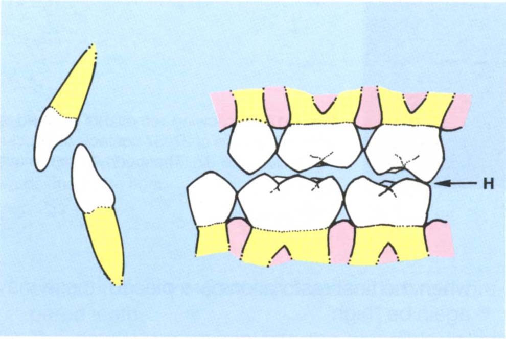
Fig. 4-12a CRCP – Initial contact between 27 and 37 (H).
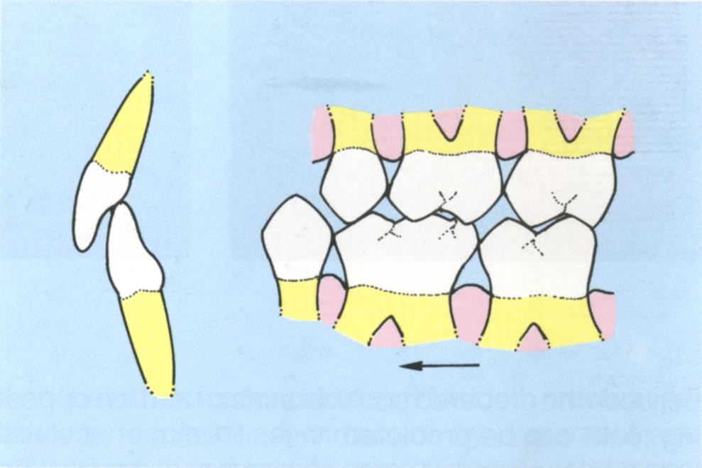
Fig. 4-12b IP – The mandible is more anterior than in (a) avoiding the deflective contact between 27 and 37.
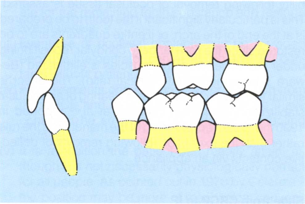
Fig. 4-12c 26 prepared for a crown, the deflective contact has not been touched and, therefore, the IP is retained.
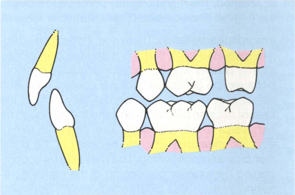
Fig. 4-12d 27 prepared for a crown: in so doing the deflective contact has been removed.
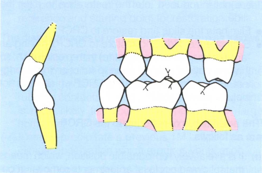
Fig. 4-12e The original IP may be retained, and there is room for the restoration.
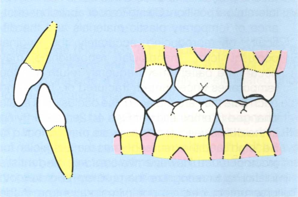
Fig. 4-12f Adaptation may occur: the mandible moving along a new path of closure, resulting in insufficient room for the restoration.
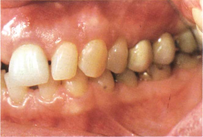
Fig. 4-12g Bridge from 25-27 to be replaced.
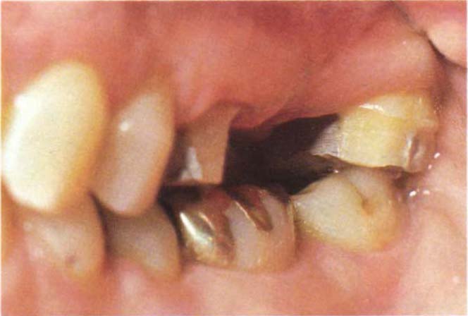
Fig. 4-12h Following removal of the bridge and preparation of 27, 37 contacts the occlusal surface of 27. The condyle has move superiorly.
The second possibility is that the tooth or teeth to be prepared are initial contacts in centric relation position (Fig 4-12d). In this case the possible results are:
(i) IP retained. The mandible may continue to move to the original IP on closure (Fig 4-12e).
(ii) Immediate adaptation. There is an immediate adaptive response such that the mandible now closes slightly distally to the original intercuspal position, because the deflective occlusal contact has been removed (Fig 4-12f). The dentist may instruct the patient to close his mouth and find that although he removes 1 mm of tooth structure, only 0.25 mm of occlusal clearance occurs, because of the distal mandibular repositioning. This may also be accompanied by superior positioning of the condyle, resulting in even less clearance between opposing teeth. This is particularly liable to occur when the last tooth in the arch is prepared.
(iii) Delayed adaptation during temporary stage of treatment. The teeth are prepared and temporary restorations placed. The patient maintains the original intercuspal position. Owing to poor abrasion resistance of temporary plastic materials and the difficulty of reproducing accurately the original occlusal form, mandibular repositioning may occur. The patient may frequently return with the temporaries uncemented, fractured or “high” and each time they are replaced, the occlusion is again changed (Combination of Figs 4-12e, f). On trying in the definitive restorations these may be found to be “high” and the dentist blames the technician for incompetence. However, the error was the dentist’s for failing to recognize the problem prior to tooth preparation. If the temporary restorations are made out of occlusion, mandibular repositioning may occur without any occlusal discomfort. However, when the final restorations are placed, these may again be “high”.
If the tooth to be prepared is the initial contact in the centric relation position, it is prudent to investigate the occlusion further and adjust the occlusal contacts on this tooth prior to preparation (Figs 4-12g, h). Only proceed with crown preparations when posterior stability following removal of occlusal tissue is assured. This is particularly significant if the tooth to be prepared is at the end of the arch, or if entire quadrants are to be restored since the resistance to condylar repositioning under the influence of the muscles is eliminated (Beware a large horizontal : vertical ratio). The effect is similar to that which results from wearing of an occlusal stabilization appliance. Carossa et al.30 reported in 1990 that distal repositioning of the mandible is the rule rather than the exception following removal of deflective contacts via an appliance.
Slide from CRCP to IP
If restorations are required and a slide is present, the dentist must decide whether to:
- Restore to the IP, maintaining the original deflective contacts and ensuring that new deflective contacts are not introduced into the restoration to alter the slide.
- Eliminate the slide and restore to CRCP.
- Eliminate the slide and restore to CRCP, leaving an “area of freedom” (long centric) in the restoration, so that the patient can continue to function in the original IP or on an area anterior to CRCP which does not include the original IP.
The advantages of restoring to the CRCP are as follows:
(i) It is a relatively reproducible position, which means that following occlusal adjustments removal of occlusal tissue during tooth preparation will not result in mandibular repositioning with associated decrease in the inter-occlusal clearance between prepared teeth.
(ii) The dentist can manipulate the mandible to the desired vertical dimension and establish tooth to tooth contacts without “patient interference”. He is, therefore, able to establish occlusal contacts on the restorations which, by controlling the location and direction of occlusal loads, are also most appropriate for the remaining tooth substance and restorative materials.
(iii) Evenness of occlusal contacts can be provided because the operator can establish and test contacts without patient guidance.
(iv) AII movements occur in an anterior direction from the CRCP and the clinician can, therefore, have control, if he so desires, of potential contacting surfaces.
(v) It is a position the patient can readily attain, although it is not necessarily physiologically correct for all people. As pointed out in 1978 by Celenza23 the position may be more of mechanical convenience than physiological correctness.
(vi) CRCP can be transferred to an articulator, and small changes in vertical dimension accurately made, if necessary, such that the tooth to tooth contacts established will be the same as those in the patient’s mouth. Thus, it is a useful (initial) reference and starting point for restoration.
The disadvantages of restoring to CRCP are as follows:
(i) The patient may be made occlusally aware.
(ii) If the mandible moves a long way distally, the anterior guidance may be lost, leading to posterior rubbing contacts. This is a major disadvantage and is most likely to occur in the patient with large horizontal : vertical ratios between CRCP and IP.31
(iii) It may reprecipitate a previous TMJ click. This is a clinical observation which requires verification.
The findings of the examination will determine whether CRCP or IP is chosen for the fabrication of restorations. When a slide is eliminated, it is imperative that it be carried out prior to definitive tooth preparation, either by occlusal adjustment or by placement and adjustment of temporary or provisional restorations. Adjustment continues until the CRCP is clinically reproducible, only then can the definitive restorations be provided with confidence.
Significance of the Direction of the Slide
Anterior slide. An anterior slide occurs when the slide from CRCP to the IP is straight forward. If the tooth which is to be prepared makes no contact in the slide ensure that the restoration also makes no contact. If the tooth which is to be restored is the deflective contact inducing the slide, it is important to adjust the occlusion on this tooth prior to restoration to ensure that removal of occlusal tissue during preparation will not result in mandibular repositioning (Figs 4-12a-f). This becomes even more important when an entire quadrant has to be restored.
Alternatively, the original cuspal inclines must be accurately reproduced in both the temporary and final restorations in order to reproduce the slide – a difficult exercise. However, this may be necessary for the patient who has a prior history of reciprocal clicking and a large horizontal : vertical ratio between the centric relation and intercuspal positions. This will be described further in the Significance of the Nature of the Slide.
Lateral slide (Fig 4-13). If the slide from the CRCP to the IP is forwards and inclines to one side, or just inclines to one side, it should usually be eliminated prior to the restoration, that is, when:
(i) The tooth to be restored is a deflective contact.
(ii) The tooth to be restored is contacted during the slide, such as, the upper anterior teeth which have porcelain jacket crowns and are traumatised by the slide from centric relation to intercuspal position.
(iii) An entire quadrant of the dentition is to be restored.
(iv) The slide between CRCP to IP has a large vertical : horizontal ratio.
Fig. 4-13 Lateral slide from CRCP to IP.
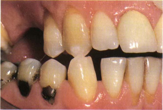
Fig. 4-13a CRCP
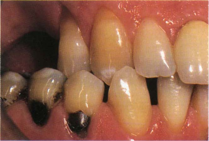
Fig. 4-13b IP. The mandible has moved forwards and to the right.
Significance of the Nature of the Slide
In 1992, Wise31 reported on the relationship between the vertical : horizontal ratio (calculated from measurements made at the incisal pin of a Denar Mk2 articulator) and the movement of the transverse condylar axis in 42 subjects free from temporomandibular disorders.
The ratios were plotted against the greatest horizontal movement of the transverse axis of either condyle for each subject (Fig 4-14a). The linear fit was computed and the correlation coefficient was 0.73. This implies that there is a direct relationship between the ratio measured at the front of the mandible and the horizontal movement of the transverse condylar axis. As the horizontal component of the slide increases compared with the vertical component, the transverse axis of the condyle moves horizontally.
Fig. 4-14 Vertical (V): horizontal (H) ratio as measured at the incisors versus greatest horizontal movement of the transverse axis as measured on the articulator (Reproduced from Wise M. D. Int J Prosthodont 1992; 5: 333-343).
 = Horizontal component greater than the vertical;
  = Vertical component greater than the horizontal.
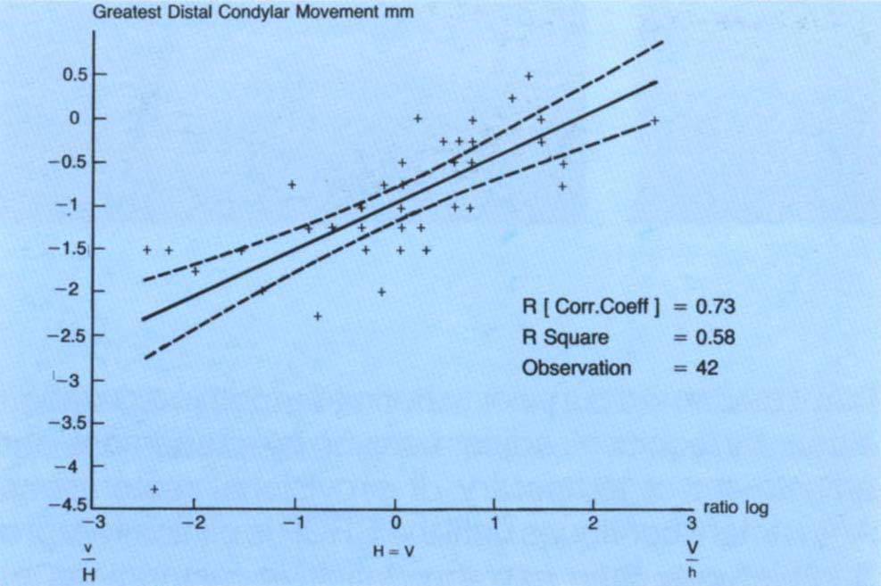
Fig. 4-14a Correlation, from 42 patients, between the greatest distal horizontal condylar movement and the log of the ratio of vertical to horizontal movement at the incisal pin. There is a straight line relationship. As the horizontal component of the movement measured at the incisal pin increases, so does the horizontal component of the condylar movement as measured on a Vericheck.
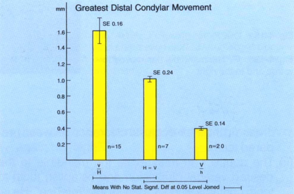
Fig. 4-14b Mean scores, from 42 patients, of the greatest distal condylar movement versus the vertical : horizontal ratio. The greatest distal movement of the condyle, as measured on the Vericheck, occurred in the group with the horizontal component being greater than the vertical component, as measured at the incisors.
When the mean values of the greatest horizontal movement of either condyle in all cases with a vertical :horizontal ratio less than one were compared with those with a ratio of one or more, it was found that the greatest mean horizontal movement of the transverse axis (1.63 mm) was related to those cases with a ratio less than one (P < 0.05) (Fig 4-14b).
Similar calculations were made to assess any relationship between the ratios and the greatest movement of the transverse axis in a vertical direction. There were no statistically significant relationships, nor were there significant differences between the means. The mean vertical movement of the transverse axis was 0.7 mm for small vertical : horizontal ratios, 0.75 mm for ratios of one and 1.11 mm for large vertical : horizontal ratios.
It can be concluded that, when the mandible moves from centric relation contact position to the intercuspal position and vice versa, the dimensions of the horizontal movement of the transverse axis of the condyles is directly related to the vertical : horizontal ratio measured at the front of the mandible. Patients with a larger vertical than horizontal component tend to have little, if any, horizontal movement of the condyles, whereas those with a larger horizontal component have a correspondingly larger horizontal movement. Vertical movement of the condyles is possible in all cases.
A slide with a large vertical : horizontal ratio is easy to adjust, as the condyle may move vertically but on average will only move horizontally by a small amount. Conversely, a slide with a large horizontal : vertical ratio is difficult to adjust as there is likely to be a large horizontal shift of the condyles.
Following adjustment the former tends to result in CRCP coinciding with the original IP and requires little adaptation by the patient. The latter frequently results in CRCP becoming distal to the original IP and may result in loss of contact between upper and lower anterior teeth, giving rise to guidance problems (Fig 4-15).
Fig. 4-15 The effect of the vertical : horizontal ratio on post occlusal adjustment mandibulo/maxillary relationships.
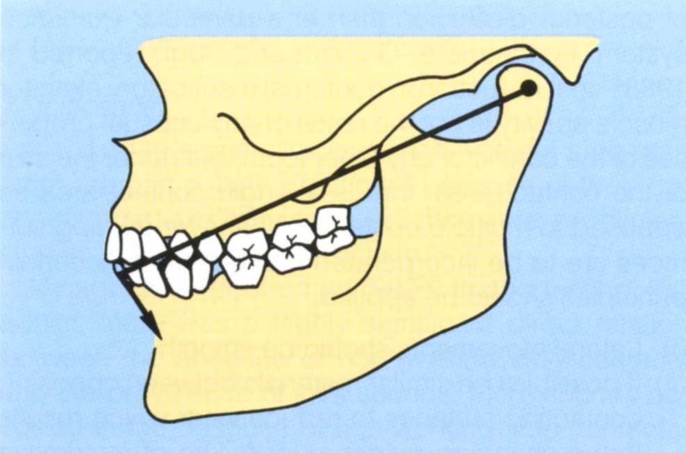
Fig. 4-15a (left) As opening occurs about the transverse condylar axis, the effect of arcing moves the mandibular incisors distally relative to the maxillary incisors.
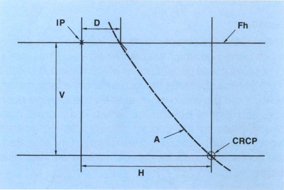
Fig. 4-15b (right) (Reproduced from Rosner D., with permission of the American Academy of Periodontology, J. Periodontology, 1973; 44: 228-235). Diagrammatic representation of the movement of a lower incisor – broken line – from CRCP to IP. Fh – Frankfort horizontal plane; IP – intercuspal position; CRCP – centric relation contact position; H – horizontal movement in the presence of a large horizontal : vertical ratio between CRCP and IP; V – the vertical movement of the lower incisor between CRCP and IP. The arcing effect due to rotation about the transverse axis would move the lower incisor along the arc of closure, resulting in a position which is distal to the IP by a dimension of D. The movement represented by D results from a horizontal movement at the condylar level. If posterior deflective contacts were removed in CRCP, the mandible would move closer to the maxilla. If removal of the deflective contacts ceased when the lower incisors reached the vertical dimension of the IP, then for a large horizontal : vertical ratio, the new position of the lower incisors would be distal to the original IP. If incisal guidance was present prior to removal of the deflective contacts, this would now be lost due to the distal positioning of the mandible.
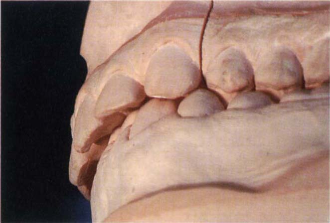
Fig. 4-15c Casts of a patient with a large horizontal : vertical ratio. Before removal of posterior deflective contacts showing the anterior relationships.
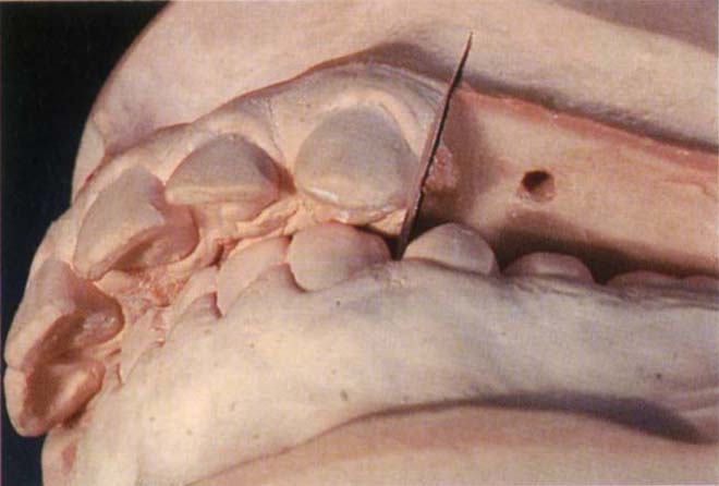
Fig. 4-15d Following removal of posterior deflective contact by removing the posterior sextants. The anterior guidance has been lost.
If the patient has a history of reciprocal clicking and a large horizontal : vertical ratio, it is prudent to retain deflective contacts so as to prevent the mandible from distally repositioning and possibly altering the condyle/ meniscal relationship (Chapter 28). If an occlusal stabilization appliance is provided for a patient with a large horizontal : vertical ratio, there is a danger in that, with an alteration of intercuspal proprioceptive input the mandible will move a long way distally. Therefore, when the appliance is removed the patient is extremely uncomfortable and is unable to revert to the original, intercuspal position.
Dimensions of the slide. Small slides may be easy to adjust but larger slides, common in Angles Class 2 division 1 cases, can be difficult to adjust and it may be difficult to obtain patient comfort. In these cases it may be better to restore to the existing IP, taking great care to ensure that it is copied accurately.
Ease of slide. If the patient has freedom between CRCP and the IP, but there are no cuspal inclines forcing the mandible into the IP, restorations should copy the existing relationship.
Patients for whom manipulation is difficult will require more time than those for whom manipulation is easy since stabilization of jaw relationships is easier and more predictable in the latter.
Lateral Positions and Excursions – Working Side Contacts
Contact between the opposing teeth on the side towards which the mandible has moved.
Location
The patient is instructed to close into the IP and then move to the side which will be investigated. Frequently, difficulties are experienced, in which case it is helpful if the patient observes the movement in a face mirror. Instruct the patient to move to the edge to edge position, and slightly beyond that which is the cross over position. Ideally the contact should also be located from the CRCP, but this is often difficult. Once located, the contacting surfaces can be marked with occlusal tapes.
Observation
When the teeth are in contact during lateral excursion it is important to consider:
- Whether there is group function (contact of two or more opposing pairs of teeth on the working side).
- Whether there is canine guidance (contact only of the opposing canines with the other teeth separated or discluded). Frequently, there will be a combination of both, so that initially there is group function, but in the edge to edge position only the canines contact.
- If the guiding teeth move excessively in their socket.
- Whether the lateral movement is smooth or restricted.
- Whether the teeth are in contact in the cross over position.
- The range of lateral movement.
Significance
Identification of the precise contacts made in lateral excursion is particularly important in patients with bruxism, as restorations may alter the direction of mandibular movement, leading to mechanical failures or discomfort. Mandibular movement is guided by condyle fossa relationships and tooth relationships.
A number of authors believe that there should only be guidance in lateral excursion on the canines,32–35 whereas others believe that there should be multiple contact on the working side,36–39 known as “group function”. An excellent review is provided by Thornton in 1990.40 Others state that in reconstruction, the guidance should be on the canines, but it should be such that, if these teeth wear, the dentition will “drop into” group function.41 The proponents of all concepts agree that non-working side contacts should be eliminated. There are no well controlled clinical studies which favour one form of guidance over the other. Several authors have reported that canine guidance reduces elevator muscle activity.42–43 However, Williamson et al. reported in 198344 that this may be more a function of posterior disclusion than of a particular guidance system. Furthermore, Graham and Rugh reported in 198845 that reduction in nocturnal masticatory elevator muscle activity is not the result of any unusual properties of the canine or any other tooth, but rather the size of the contact area, that is a single contact area as opposed to multiple contacts. Whenever guiding surfaces are to be incorporated into restorations certain principles should be applied:
(i) Lateral movements should be smooth.
(ii) If possible use similar materials between opposing contacting surfaces to reduce wear which results in the changing guidance or failure of restorative material through exposure of cement. This is of particular importance if the anterior guidance is shallow and other occlusal factors are not conducive to posterior disclusion (Chapter 17).
(iii) Possibly eliminate non-working side contacts (as discussed in Non-Working Side Contacts).
(iv) Ensure there is no excessive mobility of the guiding teeth. If present it may compromise the guidance leading to lack of control, in which case it should be attended to by elimination of disease if present and possibly by splinting.
(v) If the existing mandibular movement does not fulfil the above requirements, adjustment may be necessary prior to restoration.
(vi) If change is necessary it is technically easier to create it on a stable tooth as far forwards as possible, that is, on canine teeth rather than on posterior teeth (which are difficult to mark and to adjust for smooth guidance, as the lateral marks are short), and not on mobile teeth (where guidance would not be stable).
Lateral Positions and Excursions – Non-Working Side Contacts
These are contacts between opposing teeth on the side of the mandible that moves towards the median line during lateral excursion. Thus, in right lateral excursion, the working side is the right, and the non-working side the left.
Location
Non-working side contacts can be located at the same times as working side contacts. The dentist should support the mandible on the non-working side, as there is a tendency for the patient to “avoid” the non-working side contacts.
Observation
It is important to consider the:
- Presence of any non-working side contacts.
- Mobility of teeth on the non-working side.
- Associated working side contacts.
Significance
According to some clinicians, non-working side contacts are particularly significant because of their destructive nature.46–51 However, there are no clinical studies to substantiate this claim.52–54
Minagi et al. reported in 199055 that in testing 430 adults, there was a highly significant direct relation between the absence of non-working side contacts and the prevalence of joint sounds. More sounds occurred in the absence of non-working side contacts. Karlsson et al. reported in 199256 that a rapid adaptation occurred following the insertion of non-working side interferences in 12 healthy subjects. The effects of artificially placed non-working side contacts are considered further on page 389.
It is apparent, however (Fig 4-16), that non-working side contacts could result in guidance on the non-working side being controlled by tooth contact, rather than condylar movement against the meniscus and fossa. If the teeth to be restored form non-working side contacts, elimination of occlusal tissue during preparation will alter the guidance of the mandible and it may not be possible to eliminate these contacts on a subsequent restoration (Fig 4-16c). Non-working contacts on restorations produce horizontal forces which can lead to mechanical failure of the restoration or tooth (pages 210 and 291). If occlusally aware the patient may be uncomfortable with such contacts.
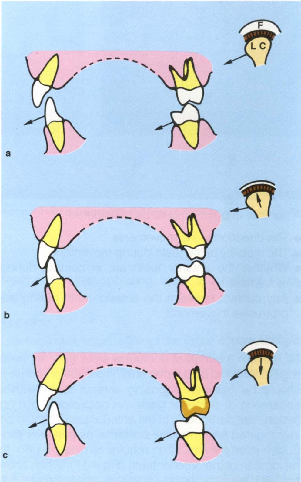
Fig. 4-16 Diagrams to show the relationships between condylar guidance, a non-working side contact and anterior guidance. Frontal view at three levels showing 13, 43, 27, 37, the left condyle (LC) and fossa (F).
a In right lateral excursion the guidance is primarily from 27 palatal cusp against 37 buccal cusp (non-working side contacts). The left condyle is not seated in the fossa due to the cuspal contact, but since adaptation has occurred over many years the patient is relatively comfortable.
b 27 prepared for a crown. In the right lateral excursion 13 and 43 now contact and muscle contraction moves the left condyle higher into the fossa. A temporary crown is placed.
c New crown positioned on 27. The shape of the palatal cusp differs from that in (a). During a right lateral excursion the left condyle is again moved interiorly. Frequently, the patient will complain that 27 is high and the dentist starts to grind it only to go through the crown or break the porcelain on a ceramometal restoration. The net result is usually to blame the technician whereas the fault is the dentist’s.
Non-working side contacts are particularly significant if associated with lateral pterygoid sensitivity on the same side. In such cases removal of these contacts prior to restoration is desirable. Non-working side contacts can only be removed if there are working side contacts to pick up the guidance (Fig 4-16b).
Protrusive Positions
These are two relationships: Straight protrusion and lateral protrusion, that is, movement forward and movement slightly to one side.
Location
For straight protrusion, instruct the patient to close into the IP and then slide straight forward until the incisors meet edge to edge. Again the use of a face mirror simplifies the procedure. Similarly, for a lateral protrusion, instruct the patient to close to the IP and then move forward and to one side. Contacts may be located with marking tapes (GHM Hanel Meckinzinal) held in forceps (Millers Forceps; GHM).
Observation
A number of points should be considered:
- The direction of the movements.
- The mobility of the teeth during movement.
- Whether the anterior teeth are in contact during movement.
- Any contact between the anterior teeth during the protrusive movements.
Significance
All modern theories of occlusion state that, for fixed restorations and partial dentures, in protrusion, contact should be between opposing anterior teeth, with a separation of posterior teeth. An occlusion requiring restoration, particularly of the anterior teeth, should be investigated for protrusive contacts, as posterior protrusive interferences often require elimination prior to restoration of the anterior teeth (Fig 4-17). When anterior teeth are crowned, the dentist must decide whether he will copy the existing anterior guidance or alter it. The existing guidance should be copied if there are no signs or symptoms, or if only anterior crowns are required for an elderly patient with an adaptive occlusion.
Fig. 4-17 Protrusive interference.
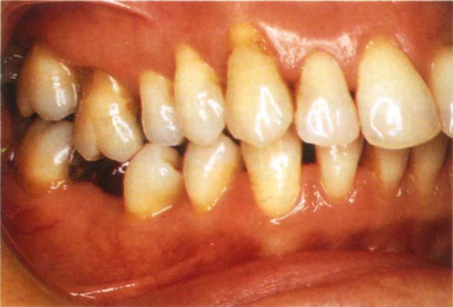
Fig. 4-17a IP
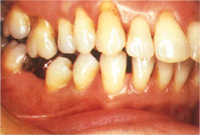
Stay updated, free dental videos. Join our Telegram channel
VIDEdental - Online dental courses


