CHAPTER 32
Alloplastic Reconstruction (TMJ Concepts) of the Temporomandibular Joint and Associated Structures
John N. Kent1 Christopher J. Haggerty2 Billy Turley3 and Robert M. Laughlin4
1Department of Oral and Maxillofacial Surgery, Louisiana State University Health Sciences Center, New Orleans, USA
2Private Practice, Lakewood Oral and Maxillofacial Surgery Specialists, Lees Summit; and Department of Oral and Maxillofacial Surgery, University of Missouri–Kansas City, Kansas City, Missouri, USA
3Department of Oral and Maxillofacial Surgery, Navy Medicine Support Command, Jacksonville, North Carolina, USA
4Department of Oral and Maxillofacial Surgery, Naval Medical Center San Diego, San Diego, California, USA
A method for reconstructing temporomandibular joints (TMJs) that have become significantly impaired and require alloplastic reconstruction to return form and function.
Indications
- Ankylosis: An alternative to soft or hard tissue grafting procedures
- Degenerative joint disease, rheumatoid arthridities, or related arthropathies and autoimmune disorders of the condyle: An alternative to soft or hard tissue grafting procedures
- Condyle loss from trauma, pathology, or any progressive disease states
- Failed autogenous joint reconstruction
- Failed alloplastic joint reconstruction
- History of multiple joint surgeries
- Loss of lateral pterygoid function with any of the above
- Vertical dimension loss of the ramus with occlusal abnormalities
- Relative indications: Pain, loss of interincisal opening, and/or occlusion disharmony refractory to non-total joint procedures
Contraindications
- Active or suspected infections in or about the implantation site
- Proven allergic reactions to any of the prosthetic materials
- Skeletal immaturity
- Systemic disease with increased susceptibility to infection
- Psychiatric disorders
- Medically compromised individuals: the very elderly, uncontrolled systemic diseases, and drug and/or alcohol addiction
Diagnosis and Surgical Planning
The surgeon must diagnose all preoperative conditions and plan desired outcomes relative to joint pathology, functional goals, desired occlusion, and aesthetics. A one-stage surgical reconstruction using a one-piece or two-piece stereolithic model, or a two-stage surgical procedure (which predominately uses a one-piece stereolithic model), is selected based on the surgeon’s preference and desired treatment objectives.
One-Stage Alloplastic Reconstruction Using a One-Piece or a Two-Piece Stereolithic Model
Specific Indications for a One-Piece Stereolithic Model
- The patient is able to maintain a normal occlusion during the computed tomography (CT) scan. Aesthetics are satisfactory.
- The surgeon is able to manipulate and maintain a normal occlusion with the use of intermaxillary fixation (IMF) for the CT scan. Aesthetics are satisfactory.
- The occlusion is ideal or nearly ideal, and it is maintained during the CT scan. Fossa anatomy is easily adjusted with minor corrections at planned surgery. Aesthetics are satisfactory.
To fabricate a one-piece stereolithic model, a manufacturer-specific CT scan is obtained with the jaws in occlusion, utilizing intermaxillary fixation if necessary. The stereolithic model is fabricated in one piece, with the patient’s mandibular dentition fused to the maxillary dentition. The custom joints are fabricated based upon the occlusion set during the manufacturer-specific CT scan.
Specific Indications for a Two-Piece Stereolithic Model
- A two-piece stereolithic model is preferred when simultaneous mandibular and/or maxillary repositioning is required. A two-piece model is necessary when performing a condylectomy and placing total joints to improve occlusion and aesthetics. In the above instances, the fossa anatomy is normal or near-normal, requiring little alteration, and joint placement improves the occlusion. Simultaneous orthognathic surgery with total joint placement can also be performed in patients with poor occlusion, specific edentulous cases, apertognathia, maxillary or mandibular deformities, and mandibular asymmetries. The surgeon must be comfortable in simultaneously reestablishing the occlusion through orthognathic surgery and performing total joint surgery. When in doubt, it is always best to plan a two-stage surgical reconstruction to reposition the mandible or maxilla through orthognathic surgery first to obtain the desired occlusion. The manufacturer-specific CT scan may then be performed with the patient in normal occlusion, with or without intermaxillary fixation, to obtain a one-piece stereolithic model.
To fabricate a two-piece stereolithic model, a manufacturer-specific CT scan is obtained with the jaws set slightly apart. The stereolithic model is fabricated in two pieces, with the mandible separated from the maxilla. The surgeon establishes the final occlusion during the surgical workup, and the custom joints are fabricated based on the desired final occlusion. The occlusion and desired aesthetics are then corrected at surgery with custom total joint placement and, if required, simultaneous orthognathic surgery.
Note: Many ankylosis patients with acceptable occlusion require only one-stage surgery using a one-piece model as minor alterations of the joint anatomy on the model are easily produced at surgery when placing the prostheses.
Two-Stage Alloplastic Reconstruction
Cases with abnormal joint pathology, mostly extensive bony ankylosis with or without occlusal or aesthetic anomalies, require excision of the ankylosis, shaping of fossa anatomy, and correction of occlusion and facial aesthetics by repositioning the mandible. Intermaxillary fixation is required immediately after the first surgery to obtain the manufacturer-specific, CT scan–generated stereolithic model for a one-piece model. The custom total joint prosthesis is inserted at the second surgical procedure. If orthognathic surgery is planned, it may be performed at either the first or second surgery. If performed at the second surgical procedure, the teeth are separated when obtaining the manufacturer-specific CT scan, and a two-piece stereolithic model will be ordered as described above.
Specific Indications for Two-Stage Alloplastic Reconstruction
- Fossa or condyle anatomy that requires significant modification or resection
- Significant bony ankylosis
- When significant occlusal alterations are necessary with (1) or (2)
- Resection of large tumors of the temporomandibular region with associated hard tissue defects
- Removal of failed alloplastic hardware
TMJ Concepts Workup
- A manufacturer-specific, medical-grade CT scan is ordered to reflect 0.5 to 1.0 mm cuts at zero gantry in an axial plane. The scan must include, at a minimum, 2.5 cm above the glenoid fossa and the complete inferior border of the mandible. The patient is scanned in occlusion (a one-piece model) with or without intermaxillary fixation or with the jaws set apart (a two-piece model), as determined by the surgical plan.
-
DICOM files are sent to the total joint manufacturer on a CD or uploaded directly for the fabrication of a stereolithic model in one or two pieces as prescribed by the surgeon. Stone models, intraoral digital scanner generated data (Figure 32.1), or cone beam CT (CBCT) scanner generated data can be used to remove scan distortion from dental artifacts (i.e., dental restorations, arch bars, and orthodontic brackets), maximize occlusal anatomy, and establish ideal occlusion when a two-piece stereolithic model is used. Utilizing the above modalities will significantly improve the accuracy of the final occlusal result. The dental anatomy data from the laser-scanned stone models, intraoral scanner, or CBCT are registered within the manufacturer’s software using surface-based alignment algorithms and are used to replace the maxillary and mandibular teeth (Figures 32.2 and 32.3) within the manufacturer-specific CT scan. Once the dental anatomy is registered to the bony anatomy within the manufacturer’s software, a hybrid model is generated, and the preferred occlusion can be produced. Either the surgeon can use the improved hybrid pieces in a two-piece model to set the occlusion, or a planned occlusion can be generated using the dental stone models. If dental stone models are used to generate the final occlusion, the stone models are scanned in a prescribed or “ideal” occlusion using one of the methods listed above. The scanned occlusion is registered to the maxilla hybrid component in the CT scan. The hybrid mandible is located to the digitized occlusion. The stereolithic model is then fabricated for subsequent implant design (Figure 32.4).
- For a one-stage procedure, a one-piece stereolithic model is returned to the surgeon with the teeth in ideal occlusion as placed by the surgeon prior to the manufacturer-specific CT scan, or the ideal occlusion is set by the surgeon on stone models, which are sent to the manufacturer for scanning if the CT was taken with the teeth apart. When the stereolithic model is returned to the surgeon, a condylectomy and coronoidectomy and minor alterations of the fossa are performed by the surgeon on the stereolithic model. The manufacturer will typically place an osteotomy line for the condyle resection and inscribe desired alteration of fossa anatomy or surface of the ramus as a guide for the surgeon.
- If the surgeon repositions the mandible on the returned stereolithic model, preservation of the coronoid processes may be helpful in maintaining the normal spatial relationships of the mandible to the skull base (Figure 32.4). Once the mandible is secured to the maxilla with hot glue or plates, the coronoids can be removed from the model. Repositioning of the maxilla may also be performed by the surgeon as needed.
- For two-stage surgical procedures, the condylectomy with fossa shaping and coronoidectomy is completed on the patient. Orthognathic surgery, if necessary, is usually done at this time. A manufacturer-specific CT scan is obtained after resection of the condyle, coronoid, or temporal mass with the patient in occlusion for the fabrication of a one-piece model or not in occlusion for the fabrication of a two-piece model if additional surgery is planned (rarely).
-
The operated model is returned to the manufacturer, who creates a wax-up of the custom prostheses (glenoid fossa and condyle) (Figure 32.22) and sends the wax-up to the surgeon for approval prior to fabrication of the total joints. The surgeon approves or requests modification of the manufacturer’s workup. The final custom prosthesis is approved by the surgeon and fabricated (Figures 32.4, 32.7, 32.9, 32.23, and 32.37). Custom-cut guides may be generated for use during condylectomies and coronoidectomies to minimize errors and to allow for a precision fit of the prostheses.
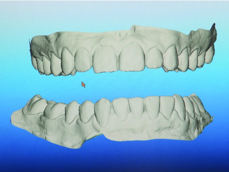
Figure 32.1. Intraoral digital scanner used to capture the surface topography of the dentition. The data is exported to the manufacturer in the form of STL files.
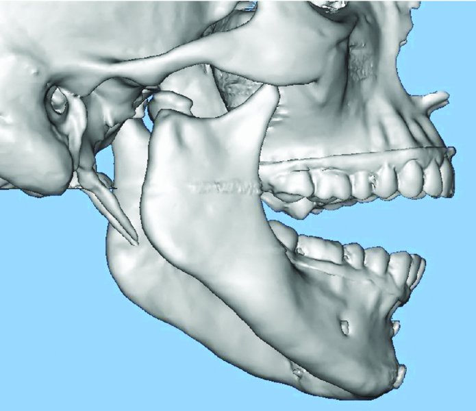
Figure 32.2. Two-piece stereolithic model of a patient with a previously treated medially displaced condyle and symphysis fracture, with resultant temporomandibular joint dysfunction and malocclusion. Stone model dental anatomy has been integrated with manufacturer-specific computed tomography in order to establish dental anatomy free of scan artifacts. Image provided courtesy of TMJ Concepts (Ventura, California).
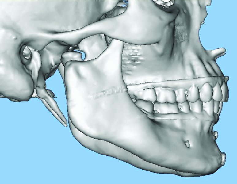
Figure 32.3. Occlusion is determined and transferred to the manufacturer-specific, computed tomography–generated 3D model. Image provided courtesy of TMJ Concepts (Ventura, California).
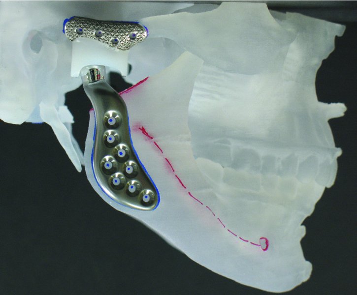
Figure 32.4. Stereolithic model with ideal occlusion established and the right total joint in place after condylectomy with coronoid preservation to allow for orientation of the normal spatial relationships of the mandible to the skull base. Image provided courtesy of TMJ Concepts (Ventura, California).
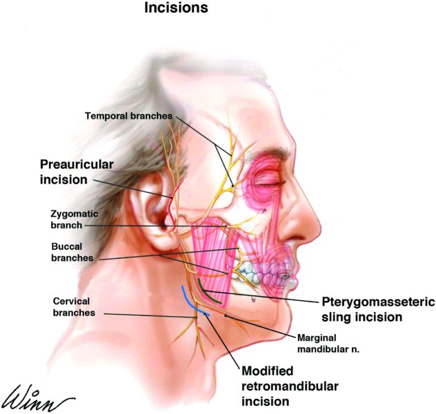
Figure 32.5. Anatomy of the facial nerve and location of the pre-auricular and modified retromandibular approach incisions. The red line depicts the location of the pre-auricular incision. The blue line depicts the location of the modified retromandibular incision. The green line represents the surgical division of the masseter muscle between the marginal mandibular and the buccal branch of the facial nerve to gain access to the lateral ramus.
Figure 32.6. When possible, the anterior aspect of the condyle can be secured to the superior mid-ramus to preserve the function of the lateral pterygoid muscle.
Figure 32.7. One-piece stereolithic model depicting reconstruction of the left mandible with a custom total temporomandibular joint prostheses following hemi-mandiblectomy for ameloblastoma.
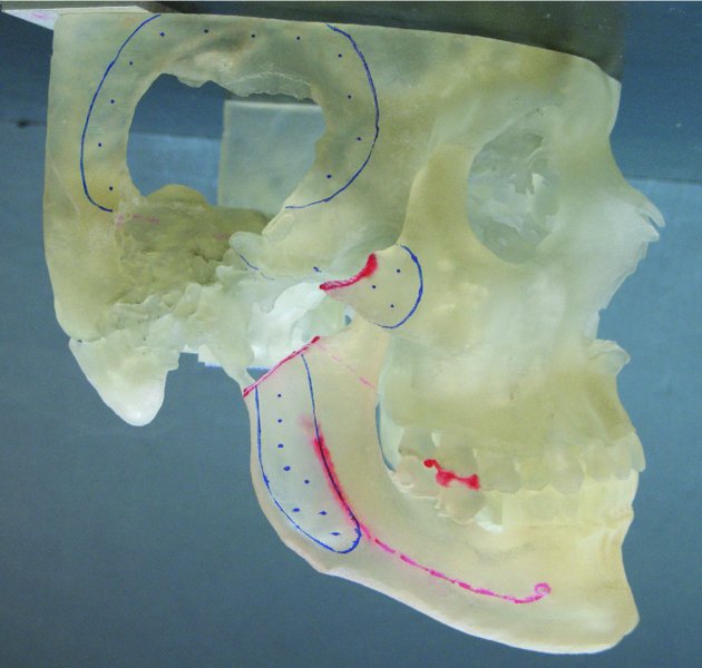
Figure 32.8. One-piece stereolithic model depicting pathological loss of the glenoid fossa, a significant portion of the squamous portion of the temporal bone, the zygomatic arch and the condylar head. Image provided courtesy of TMJ Concepts (Ventura, California).
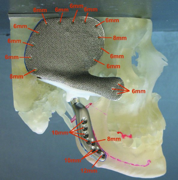
Figure 32.9. One-piece stereolithic model depicting complex reconstruction of the glenoid fossa, temporal bone, zygomatic arch, and condyle. Image provided courtesy of TMJ Concepts (Ventura, California).
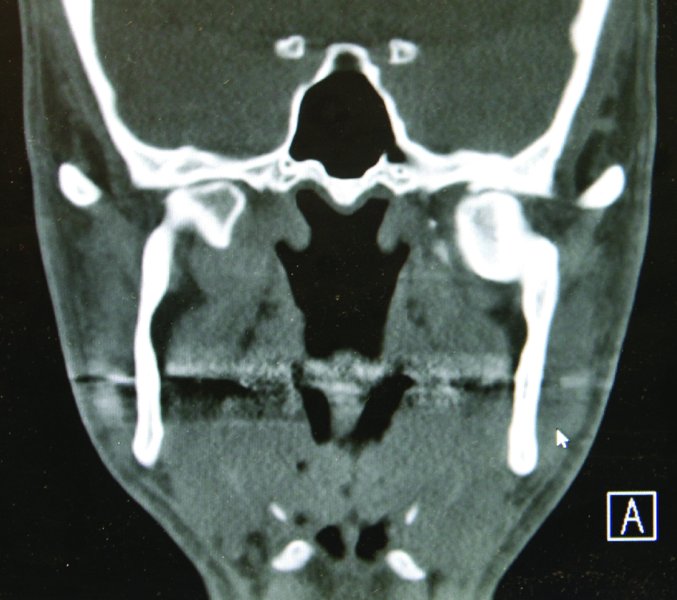
Figure 32.10. Coronal computed tomography scan demonstrating bilateral temporomandibular joint ankylosis from previous medially displaced condyle fractures.
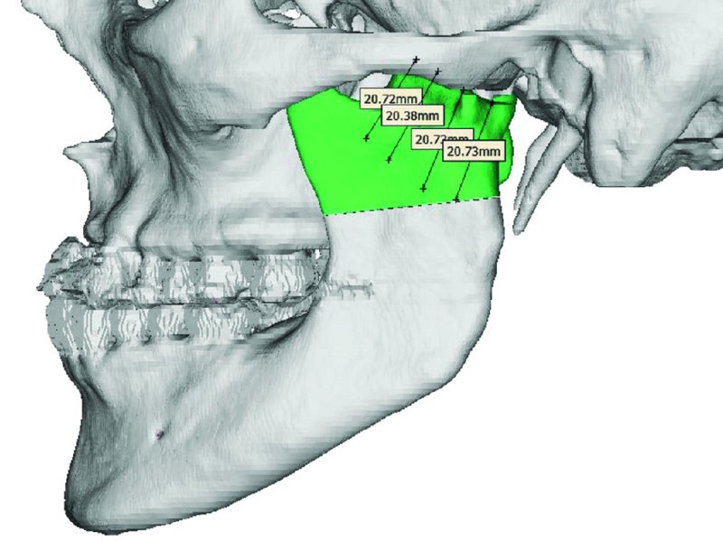
Figure 32.11. Virtual Surgical Planning (VSP) permits the identification of anatomical markers and allows for determination of osteotomy location and design. Measurements are taken from known, uninvolved structures such as the zygomatic arch. Custom cut guides may be fabricated based on VSP treatment sessions.
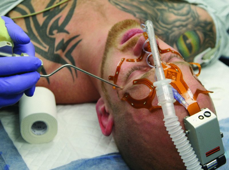
Figure 32.12. Electrodes are positioned and referenced that will be detected with the Stryker Navigation System’s software. The Navigation System enables exact osteotomy planning and execution.
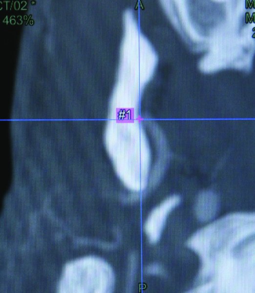
Figure 32.13. The computed tomography (CT) scan and CT angiogram are integrated into the Stryker Navigation System, and a cut plane is determined superior to the internal maxillary artery.
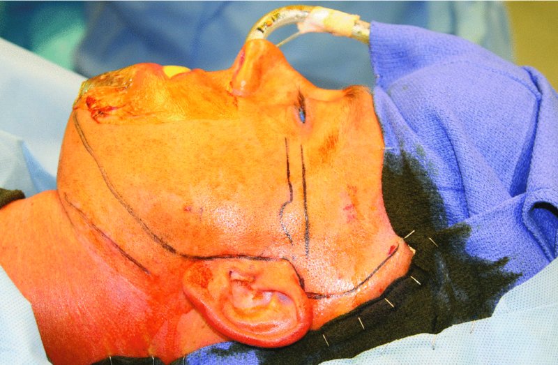
Figure 32.14. The patient is prepped and draped, a sterile, antibiotic-impregnated ear wick is placed within the bilateral external auditory canals, and the oral cavity is covered with a plastic adhesive drape to prevent the contamination of the extraoral surgical sites with oral microbes.
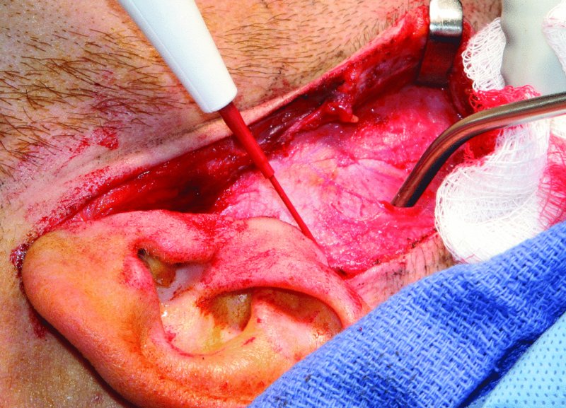
Figure 32.15. The pre-auricular incision is initiated, and the superficial layer of the temporalis fascia is exposed above the zygomatic arch.
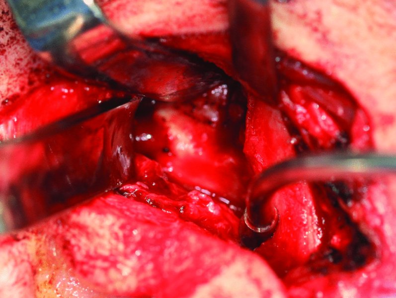
Figure 32.16. The zygomatic arch is exposed anterior to the eminence, the head of the condyle and ankylosed mass is exposed, and a cleavage plane is identified between the glenoid fossa and the condyle and ankylosed mass.
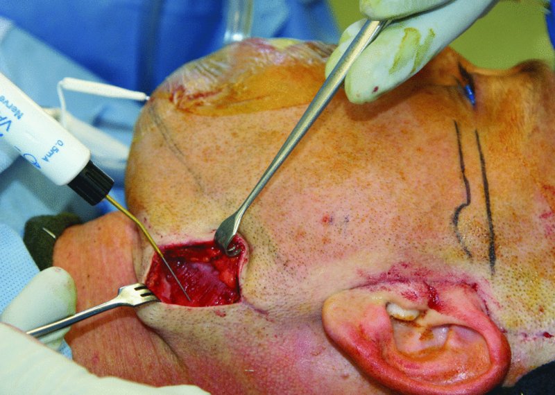
Figure 32.17. A nerve stimulator set at 2 mA is used to test for branches of the facial nerve during both the modified retromandibular and the pre-auricular approaches.
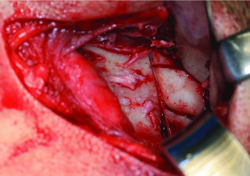
Figure 32.18. A Sonopet Ultrasonic Aspirator (Stryker, Kalamazoo, MI, USA) is used to section the ankylosed mass into small segments to facilitate the atraumatic removal of the bone from the modified retromandibular incision.
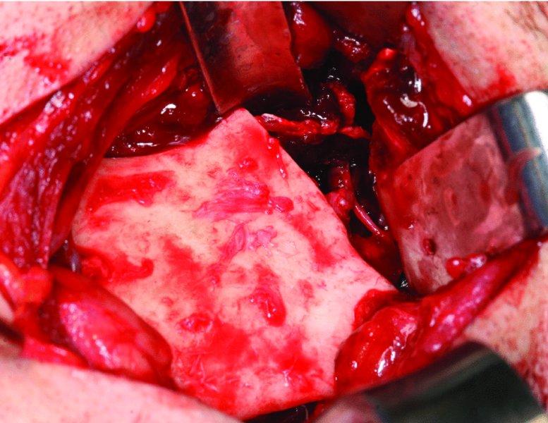
Figure 32.19. The upper ramus resection is completed and includes the medially displaced condyle, the coronoid process and the ankylosed mass. All bony irregularities that could interfere with custom joint fabrication and seating are removed from the ramus and glenoid fossa.
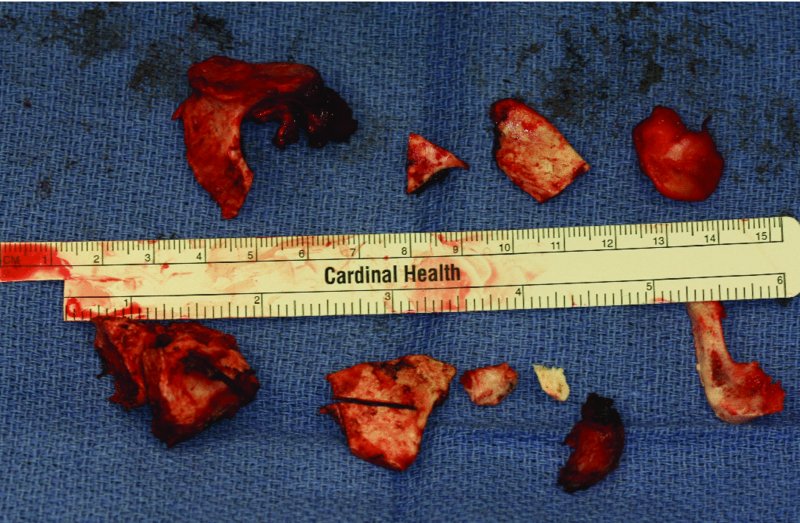
Figure 32.20. Resected ankylosed bone from the bilateral upper ramus resections, condylectomies, and coronoidectomies.
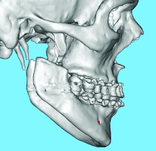
Figure 32.21. Postoperative sagittal 3D scan depicting bilateral temporomandibular joint resections. The patient is placed within intermaxillary fixation during this scan in order to establish the postoperative occlusion and to create a one-piece stereolithic model.
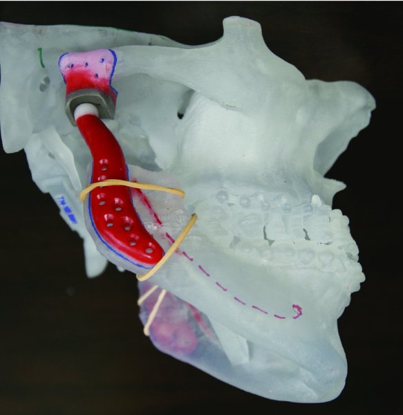
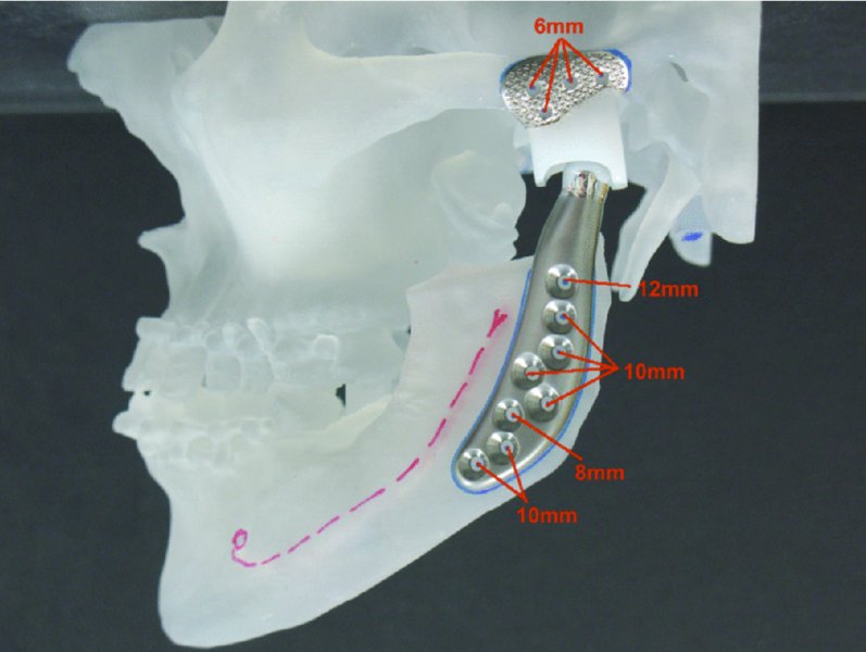
Figure 32.22. Wax-up of temporomandibular joint custom prostheses on a one-piece stereolithic model.
Stay updated, free dental videos. Join our Telegram channel
VIDEdental - Online dental courses


