28 CONNECTORS FOR PARTIAL FIXED DENTAL PROSTHESES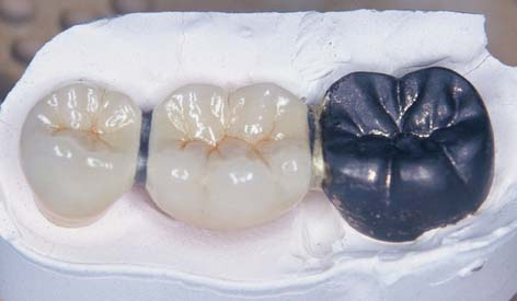
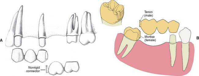
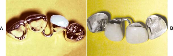
Connectors are the components of a partial fixed dental prosthesis (FDP) or splint that join the individual retainers and pontics together. Usually this is accomplished with rigid connectors (Fig. 28-1), although nonrigid connectors are occasionally used. The latter are usually indicated when it is impossible to prepare a common path of placement for the abutment preparations for a partial FDP (Fig. 28-2A and B). Their use has been reported to be associated with significantly reduced failure rates.1
RIGID CONNECTORS
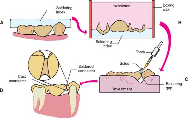
Rigid connections in metal can be made by casting, soldering, or welding. Cast connectors are shaped in wax as part of a multiunit wax pattern. Cast connectors are convenient and minimize the number of steps involved in the laboratory fabrication. However, the fit of the individual retainers may be adversely affected because distortion more easily results when a multiunit wax pattern is removed from the die system. Soldered connectors involve the use of an intermediate metal alloy whose melting temperature is lower than that of the parent metal (Fig. 28-3). The parts being joined are not melted during soldering but must be thoroughly wettable by liquefied solder.2 Dirt or surface oxides on the connector surfaces can reduce wetting and impede successful soldering; for example, the solder may melt but does not flow into the soldering gap. Welding is another method of rigidly joining metal parts. In welding, the connection is created by melting adjacent surfaces with heat or pressure. A filler metal whose melting temperature is about the same as that of the parent metal can be used during welding.
In industrial metalworking, a distinction is made between soldering, in which the filler metal has a melting point below 450°C (842°F), and brazing, in which the filler has a melting point above 450°C.3 Rigid connections in dentistry are generally fabricated above 450°C, but the process has almost always been referred to in the dental literature as soldering. However, in a proposed international standard, the term brazing is used. With time, the latter term may become more generally accepted. In this text, however, the term soldering is used.
NONRIGID CONNECTORS
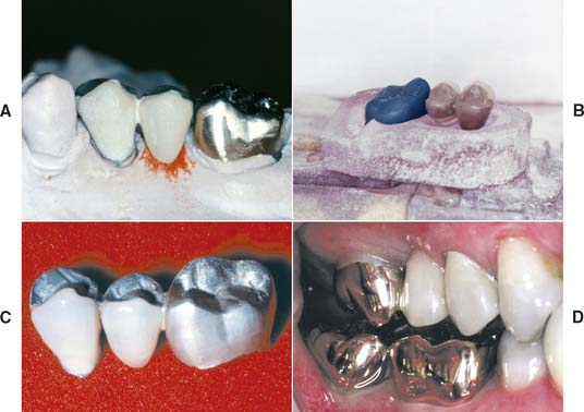
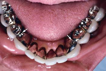
Nonrigid connectors are indicated when it is not possible to prepare two abutments for a partial FDP with a common path of placement. Segmenting the design of large, complex FDPs into shorter components that are easier to replace or repair individually is advisable. This can be helpful if there is uncertainty about an abutment’s prognosis. If the abutment fails, only a portion of the FDP may need to be remade. In the mandibular arch, nonrigid connectors are indicated when a complex FDP consists of anterior and posterior segments. During the mandibular opening and closing stroke, the mandible flexes mediolaterally.4 Rigid FDPs have been shown to inhibit mandibular flexure, and extensive splints have been shown to flex during forced opening.5 The associated stresses can cause dislodgment of complex FDPs. Segmenting complex mandibular FDPs can minimize this risk (Fig. 28-4).
CONNECTOR DESIGN
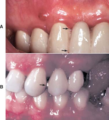
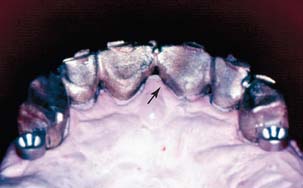
The size, shape, and position of connectors all influence the success of the prosthesis. Connectors must be sufficiently large to prevent distortion or fracture during function but not too large; otherwise, they interfere with effective plaque control and contribute to periodontal breakdown over time. Adequate access (i.e., embrasure space) must be available for oral hygiene aids cervical to the connector. If a connector is too large incisocervically, hygiene is impeded, and over time, periodontal failure will occur (Fig. 28-5A). For esthetic FDPs, a large connector or inappropriate shaping of the individual retainers may result in display of the metal connector, which may compromise the appearance of the restoration and lead to patient dissatisfaction (Fig. 28-5B).
In addition to being highly polished, the tissue surface of connectors is curved faciolingually to facilitate cleansing. Mesiodistally, it is shaped to create a smooth transition from one partial FDP component to the next. A properly shaped connector has a configuration similar to a meniscus formed between the two parts of the prosthesis.
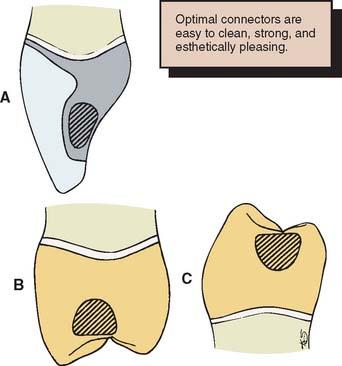
In a buccolingual cross-section, most connectors have a somewhat elliptical shape. Such an elliptical connector is strongest if the major axis of the ellipse parallels the direction of the applied force. Unfortunately, because of anatomic considerations, this cannot always be achieved. In fact, because of space constraints, the greatest dimension of most connectors is perpendicular to the direction of applied force, which tends to result in a weaker connector. For ease of plaque control, the connectors should occupy the normal anatomic interproximal contact areas, because encroaching on the buccal, gingival, or lingual embrasure restricts access. However, to improve appearance without significantly affecting plaque control, anterior connectors are normally placed toward the lingual embrasure. Figure 28-6 depicts typical locations for connectors on selected teeth.
Pulp size and clinical crown height can be limiting factors in the design of nonrigid connectors. Most prefabricated patterns require the preparation of a fairly sizable box. This allows incorporation of the mortise (see p. 843; Fig. 28-9B) in the cast restoration without overcontouring of the interproximal emergence profile. Short clinical crowns do not provide adequate occlusocervical space to ensure adequate strength. Most manufacturers recommend 3 to 4 mm of vertical height.
TYPES OF CONNECTORS
Rigid Connectors
Rigid connectors must be shaped and incorporated into the wax pattern after the individual retainers and pontics have been completed to final contour but before reflowing of the margins for investing (see Chapter 18).
Soldered connectors
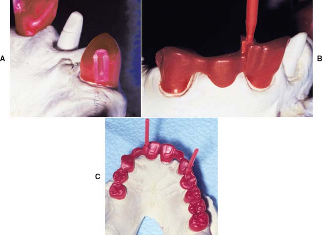
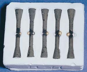
As with cast connectors, connectors to be soldered are waxed to final shape but are then sectioned with a thin ribbon saw (Fig. 28-7A and B); therefore, when the components are cast, the surfaces to be joined are flat, parallel, and a controlled distance apart. This allows accurate soldering with a minimum of distortion.6 Molten solder flows toward the location where the temperature is highest. In metal, the two flat surfaces previously created in wax retain heat, ensuring that the highest temperature is in the connector area.
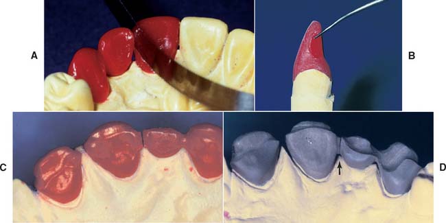
Soldering gap width
As gap width increases, soldering accuracy decreases.7 Extremely small gap widths can prevent proper solder flow and lead to an incomplete or weak joint.8 An even soldering gap of about 0.25 mm is recommended. If a connector area has an uneven soldering gap width, obtaining a connector of adequate cross-sectional dimension without resulting distortion is more difficult.
Loop connectors
Although they are rarely used, loop connectors (Fig. 28-8) are sometimes required when an existing diastema is to be maintained in a planned fixed prosthesis. The connector consists of a loop on the lingual aspect of the prosthesis that connects adjacent retainers and/or pontics.
The loop may be cast from sprue wax that is circular in cross-section or shaped from a platinum-gold-palladium (Pt-Au-Pd) alloy wire. Meticulous design is important for enabling plaque control.
Nonrigid Connectors
The design of nonrigid connectors that are incorporated in the wax pattern stage consists of a mortise (also referred to as the female component) prepared within the contours of the retainer and a tenon (male component) attached to the pontic (Fig. 28-9). The mortise is usually placed on the distal aspect of the anterior retainer. Accurate alignment of the dovetail or cylindrically shaped mortise is crucial; it must parallel the path of placement of the distal retainer (see Fig. 28-2). Paralleling is normally accomplished with a dental surveyor. When the cast is aligned, the path of placement of the retainer that will be contiguous with the tenon is identified. The mortise in the other retainer is then shaped so that its path of placement allows concurrent seating of the tenon and its corresponding retainer.
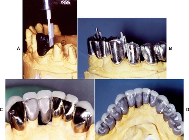
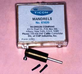
The mortise can be prepared freehand in the wax pattern or with a precision milling machine. Another approach is to use prefabricated plastic components for the mortise and tenon of a nonrigid connector (Fig. 28-10). As an alternative, a special mandrel can be embedded in the wax pattern (Fig. 28-11) and the abutment retainer can be cast, with refinement of the female component as necessary; the male key is then fabricated with autopolymerizing acrylic resin and attached to the pontic.
MATERIALS SCIENCE
Solder
Dental gold solders are given a fineness designation to indicate the proportion of pure gold contained in 1000 parts of alloy. For example, a 650-fine solder contains 65% gold. In an earlier designation,9 the solder was assigned a carat number, which indicated the gold content of the castings that were to be joined with the solder; an 18-carat solder could be used to solder castings fabricated of an alloy containing 75% gold. Because numerous alloys other than type IV gold are available today, many of which contain platinum-group metals, the carat designation is of little value.
Modern casting alloys have become so metal-lurgically complex that most manufacturers now recommend specifically formulated solders. One manufacturer (Heraeus Kulzer) classifies traditional gold-containing solders as group I and others (termed special solders) as group II. Most of these have the brand name with a “pre” or “post” designation to indicate whether the solder is to be used for joining the components before or after porcelain application. The preceramic solders are obviously high-fusing alloys, sometimes fusing only slightly beneath the softening point of the parent alloy to be joined. Ideally, they flow well above the fusion range of the subsequently applied porcelain. Postceramic solders must flow well below the pyroplastic range of the porcelain. For example, one popular silver-palladium (Ag-Pd) casting alloy has a specified melting range between 1232° and 1304°C (2280° to 2384° F). The recommended special presolder melts at 1110°C to 1127°C (2030°F to 2061°F), whereas the postsolder melts at 710°C to 743°C (1310°F to 1369°F). The porcelain fuses at about 982°C (1800°F), depending on time and temperature.
The composition of the solder determines its melting range, among other things. Some typical compositions and melting ranges are given in Table 28-1. Solder’s main requirement is to fuse safely below the sag or creep temperature of the casting to be soldered. Newer palladium casting alloys, by virtue of their higher melting ranges, have somewhat increased the reliability of the preceramic application soldering technique.10

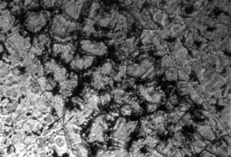
However, preceramic soldering is relatively difficult and can be structurally hazardous (Fig. 28-12). This may be because of the volatilization of base metal solder constituents that occurs with overheating.11 Volatilization then results in microporosity or pitting. The melting range of presolders is quite narrow, because silver and copper (the usual modifiers of temperature range) cannot be used in the alloy; these elements discolor porcelain on contact. Another consideration is the oxide necessary for the chemical adherence of porcelain. Porcelain does not chemically bond equally well to all solders.
Resistance to tarnish and corrosion is determined by a solder’s noble or precious metal content and its silver/copper (Ag/Cu) ratio.12 In addition, if the compositions of the solder and work piece differ, galvanic corrosion may occur.
During the soldering procedure, the solder must flow freely over clean and smooth surfaces. These surfaces should be smoothed with abrasive disks, not with rubber wheels or polishing compounds. The phenomenon of free flow is termed wetting, during which remelting or realloying of the surface of the units to be joined must not occur.13 Solder flow is increased by the addition of silver and decreased by the presence of copper. Figure 28-13 demonstrates a properly made solder joint. Note that the filler metal has joined the surfaces of the two castings without penetrating either one.
Lower-fineness gold solders are often more fluid and are generally chosen for joining castings. If necessary, proximal contacts with a solder of higher fineness can also be added, because this tends to flow less freely. However, the exact minimally acceptable fineness necessary for resisting tarnish and corrosion has not been conclusively established; 615 or 580 fineness is probably the lower limit of clinical acceptability.
The last requirement, strength, is easily satisfied by most solders and is usually greater than that of the soldered parent metal, provided that the procedure is followed carefully.8 In addition, most solders harden during cooling because of the “order-disorder” transformation and the formation of other intermetallic phases, which occur at grain boundaries. Brittleness is frequently encountered with gold-based copper-containing solders. As with type III and type IV gold casting alloys, the gold-copper order-disorder (or discontinuous phase-hardening) mechanism causes similar changes in the solder’s microstructure.14 Simply stated, with these solders, cooling to room temperature results in a brittle joint. The joints are strong but have no ductility. Some solder joints are weakened by notches.15 This means that soldered connectors should be well-polished to prevent fracture.
Soldering Flux and Antiflux
Soldering flux
Borax glass (Na2B4O7) is frequently used with gold alloys because of its affinity for copper oxides. An often-cited soldering flux formula16 is borax glass (55 parts), boric acid (35 parts), and silica (10 parts). These ingredients are fused together and then ground into a powder.
New fluxes are available for use with non–gold-based alloys. Their formulas are not generally published. At present, none of the new fluxes are totally capable of preventing oxide formation during heating of the base metal or nonnoble alloys. An example of a rapidly forming oxide on a base metal occurring during a simulated postceramic application soldering can be seen in Figure 28-14. Soldering of base metal alloys is still unpredictable.17
Soldering antiflux
Graphite (from a pencil) is often used as an antiflux. However, the carbon easily evaporates at higher temperature, leaving the work piece unprotected. A more reliable antiflux is iron oxide (rouge) in a suitable solvent such as turpentine, which can be painted on the casting with a small brush.
Soldering Investment
Soldering investments are similar in composition to casting investments (see Chapter 22). Casting investments, both gypsum and phosphate bonded, mixed with water only, have been used for soldering. However, the refractory component in casting investments usually creates unwanted thermal expansion and therefore excessively separates the units to be joined. Soldering investments ideally contain fused quartz (the lowest thermally expanding form of silica) as their refractory component.
Stay updated, free dental videos. Join our Telegram channel
VIDEdental - Online dental courses


