20
Cephalometric analysis
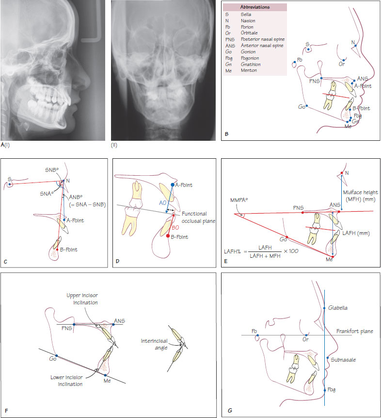
Figure 20.1 (A) (i) The lateral cephalogram. Note that the soft tissue outline is clearly visible and (ii) posteroanterior cephalogram of a patient with a mandibular asymmetry. (B) The main cephalometric points are summarised. For definitions please see Appendix 2. (C) Measurement of SNA, SNB and ANB. (D) The Wits analysis. (E) Assessment of the vertical dimension using MMPa and the lower anterior face height proportion (LAFH%). (F) Assessment of incisor inclinations and the interincisal angle. (G) Soft tissue analysis of maxillary and mandibular prominence.
Cephalometric radiography is a standardised and reproducible method of taking radiographs of the facial skeleton and cranial vault. The two cephalometric views used are the:
- lateral cephalometric view – the most commonly used and the focus of this chapter (Figure 20.1Ai);
- posteroanterior cephalometric view – used for the assessment of skeletal asymmetries (Figure 20.1Aii).
The cephalostat is a device used to standardise head position and magnification when taking cephalograms to enable comparison between sequential films. The vertical head position is standardised by placing ear posts into the external auditory meatus. The angulation of the head is standardised by ensuring that the Frankfort plane is parallel to the floor or the head is in the natural head position when the film is exposed. The magnification, usually between 5% and 12%, is kept constant by maintaining the x-ray tube to head distance (usually 150–180 cm (5–6 feet)) and head to film distance (usually 30 cm (1 foot)).
Lateral cephalometric analysis
Figure 20.1B shows the main cephalometric points and Appendix 2 lists the definitions of commonly used points and reference lines in alphabetical order. There are many hard tissue analyses and this chapter will focus on the principal components of cephalometric analysis.
Relationship of the maxilla and mandible to the cranial base
The anteroposterior (AP) position of the maxilla and mandible relative to the cranial base is represented by the angle SNA and SNB, respectively (Figure 20.1C). Table 20.1 outlines normal cephalometric values including SNA and SNB. An increased or decreased angle maybe due to protrusion or retrusion of the maxilla and mandible, respectively.
Stay updated, free dental videos. Join our Telegram channel
VIDEdental - Online dental courses


