Chapter 19
POSTERIOR TOOTH SUPPORTED CANTILEVERED PONTICS
Considerations
If removable partial dentures must be avoided and osseointegrated fixtures are not a feasible option, it is sometimes advantageous to provide posterior cantilevered pontics (Fig 19-1). The following points should be considered:
Concentration of High Stress and Strain
Glantz et al., in 1984,1 reported that the risk of mechanical failure in the form of cementation failure, abutment failure, porcelain fracture or joint failure, is much less in the cantilevered part of the construction, than in those parts immediately proximal to the distal abutment crown. In particular, ‘high strain levels were recorded mesial to this crown’. When considering the potential rotations that probably occur on axial loading of the cantilever section, it can be seen that, when there is no mobility of the distal abutment (particularly in the case of an implant when stress has strained the retaining screw and this has not been retightened [see Chapter 33]), the axis of rotation is in the vicinity of the distal gingival margin of the most distal retainer (Fig 19-1a [i]). Rotation about a distal axis (Fig 19-1a [i]) will cause the mesial surface of the retainer to engage the mesial surface of the abutment. Considering the law of the lever, Lx = Ry (Fig 18-2a) and R = Lx/y. Therefore, the closer the application of the resistance force to the axis of rotation, that is, the smaller the y value, the higher the applied force. In consequence, maximum stress and strain should occur on the mesial aspect of the distal abutment, that is, the closest resistance point to the axis. As mobility of the abutment increases, the location of the axis of rotation moves mesially (Fig 19-1a [ii, iii])2 and can be located in the joint area mesial to the abutment or somewhere between this location and the distal location. If located in the mesial joint area, this will be an area of high stress, as the construction will flex around this axis. Any imperfections in the joint can accelerate mechanical failure of the joint through crack propagation between the grain boundaries of the metal alloy. Axial loading of the cantilever also introduces a lingual rotation due to movement of the distal abutment.3
Although risk of mechanical failure is not particularly high in the cantilevered part, this assumes, with ceramo-metal restorations, that the substructure is sufficiently rigid to resist flexure and resultant fracture of the porcelain. The cantilevered portion should be waxed to full contour, as for an all gold construction, and then reduced evenly by 1 mm to produce a metal framework of optimum thickness. See the Appendix.
Fig. 19-1 Posterior cantilevered pontics.
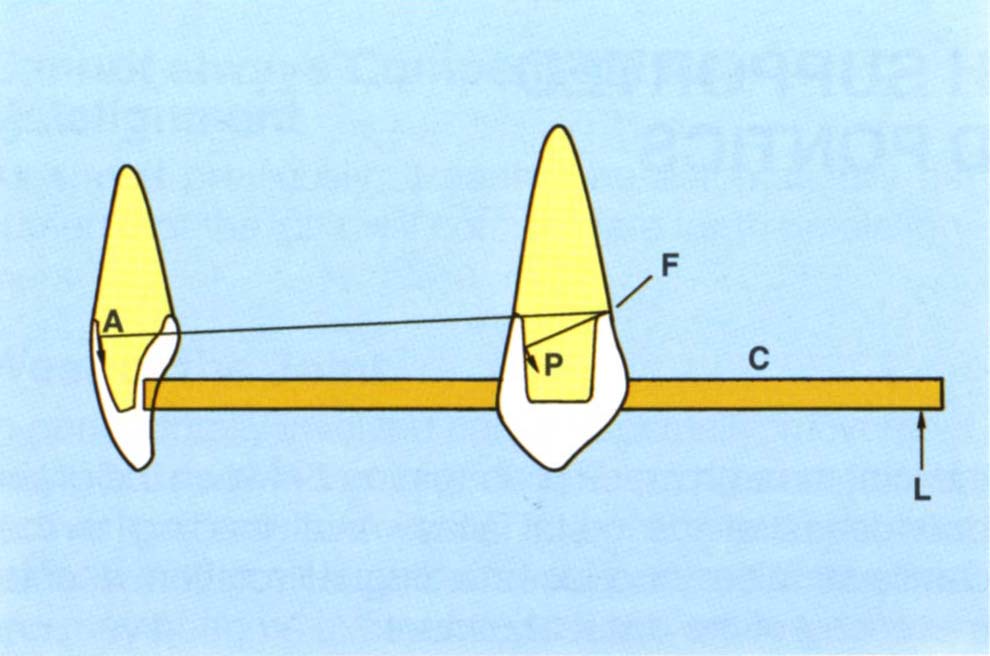
Fig. 19-1a (i) For an axial load (L) on the cantilever (C) and an implant or a tooth with virtually no clinical mobility, the axis of rotation is towards the distal margin of the distal retainer (F). Mesially facing surfaces of the posterior teeth (P) and labially facing surfaces of the anterior teeth (A) resist long axis loading of the cantilever. The greater the radius from (F) to the resisting surface, the less the load on the retainer/abutment, since the potential movement approximates the long axis of the preparation – compare A to P and since according to the law of the lever, for a given load at a fixed distance from the axis of rotation the further the resisting force is from the axis, the smaller it will be to maintain equilibrium. The closer the resisting surface is to the axis, the greater the stress on that surface. The further the resisting surface is from the axis, the lower the resisting force required to counteract the applied load. There is a bending moment about the axis.
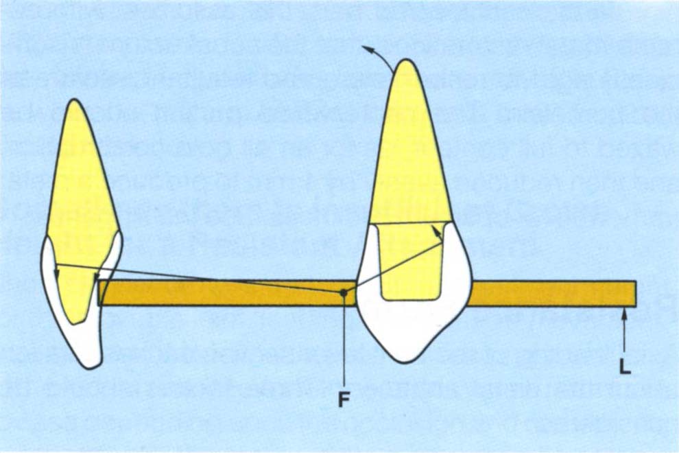
Fig. 19-1a (ii) As the mobility of the tooth increases, so the axis of rotation moves mesially and is located in the area of the joint mesial to the distal abutment (Glantz, 1993). Note that the distal tooth/retainer complex rotates about this axis. This movement of the axis of rotation applies only to teeth and not to implants.
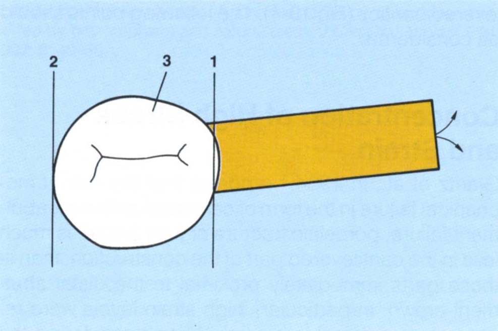
Fig. 19-1a (iii) The axis of rotation can be at 1 or 2, or at any point between them, such as, 3, depending upon the mobility of the tooth. As the axis moves mesially, the direction of rotation of the cantilever usually includes a bucco-lingual component.
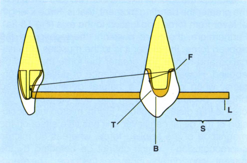
Fig. 19-1b Mesio/distal grooves in anterior teeth resist rotations resulting from long axis loading of the cantilever (L). Assuming a distal axis of rotation, distal angulation of the mesial surface of a distal abutment (T) to reduce loading on that tooth. The length of the cantilever section (S) has been reduced so as to reduce the lever effect (B = bridge made over copings).
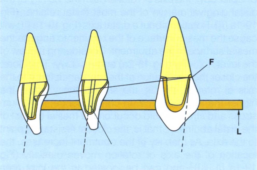
Fig. 19-1c Mesial path of insertion, made over copings, that is, the distal wall inclined mesially. This facilitates a mesial path of insertion for the anterior teeth (mesially inclined grooves) and greater resistance offered by them, for a distal, mesial or intermediate location of the axis of rotation.
Fig. 19-1d Cantilever 15, 16. Tooth 16 pontic is essentially a buccal facade for aesthetic purposes, thereby reducing the functional length.
Resistance Form
Axial loading of the cantilever section causes rotation about the distal abutment. Three factors should be considered:
- Applied force.
- Resistance angle.
- Resistance forces.
Applied Force
The further the applied force is from the axis of rotation, the greater the bending moment, that is, force x length of lever from force application to the axis (Fig 18-2a). Furthermore, the more posterior the location of the applied force, the closer it is to the muscles of mastication and hence, the greater the force that can be applied. However, in the absence of deflective contacts, when opposing a natural dentition or fixed bridge, occlusal forces on two unit cantilevers decrease in a distal direction.4 Eighty micron infraocclusion of the distal cantilever unit has little effect on the magnitude of the applied force, whereas 80 micron supraocclusion – which cannot be detected by the patient-considerably increases the force.4 The reduction in force may be due to the bending of the cantilever section.5 In contrast to an opposing natural dentition, it has been reported that two unit cantilevers opposing a complete denture do not exhibit a decrease in force along the cantilever.6 This may be due to a lack of proprioception and/or tilting of the denture. Proprioception may influence the magnitude of the applied force since loading of cantilevers decreases with decreasing periodontal ligament area of the abutments.7 In the presence of a unilateral cantilever, the non cantilever side is the preferred chewing side,7 again indicating a proprioceptive influence.
Resistance Angle
Assuming rotation about an axis in the vicinity of the distal abutment, the potential path of movement of retainers can be calculated (Fig 19-1a [i]). It can be seen that mesially facing surfaces of posterior preparations and labially facing surfaces of anterior teeth will resist rotation. Those surfaces closest to the axis of rotation will have the smallest radius and, therefore, the greatest curvature to their paths of movement. Those surfaces furthest from the point of rotation will have a lesser curvature to their movement, which/>
Stay updated, free dental videos. Join our Telegram channel
VIDEdental - Online dental courses


