Silver Amalgam
Dental silver amalgam has been an extremely effective restorative material for a very long time and, despite challenges from cosmetic dentistry and doubts about safety (it is safe), it is likely to continue to be used. While it is capable of good service, it is also subject to abuse. Correct handling will give good results but its behaviour, and the compromises that are involved, need to be understood and respected for high quality work.
In the setting reactions of dental amalgam a series of intermetallic compounds are formed as a solid matrix embedding unreacted alloy. These reactions can be traced through the relevant constitutional (phase) diagrams, although equilibrium is probably never reached. The mechanical and corrosion properties, which involve several compromises, are directly dependent on this polyphase structure. However, the path of these reactions can only be understood in terms of the constitution of the alloy, which varies according to the method and conditions of manufacture.
The mixing proportions of alloy to mercury are critical in that excess alloy is necessary for strength, yet the safety margin is small. Recent alloy compositions, often including large amounts of copper, can result in some improved properties, but the safety margin for mixing is narrowed.
The setting process is associated with dimensional changes. These must be controlled if excessive leakage or pain and cracked teeth are to be avoided. Again, this is very much a function of composition and the condition of the alloy.
Amalgam is a polyphase alloy and consequently is prone to corrosion by galvanic effects. However, this corrosion is beneficial as it normally leads to a seal being formed at the margin. More corrosion resistant formulations (high copper) may not achieve this, and involve other compromises.
Although dental amalgam is a relatively forgiving material, as a long term restorative it is jeopardized by lack of attention to the critical factors. By understanding the reactions, and recognizing the limitations of this material, sufficient control can be exercised for successful dental use.
An amalgam generally is an alloy of a metal with mercury, but in dentistry the term has adopted a more specific interpretation: the result of mixing a silver-based alloy, in the form of small particles, with mercury into a paste which then sets hard. It has been the dominant direct restorative material for many years, and it owes his popularity to a combination of useful properties: relative cheapness, easy preparation in the clinic, simple placement procedures, rapid setting, high strength. However, the apparently forgiving nature of the material is, as with many other materials in dentistry, deceptive. It must be handled with considerable care if its full potential as a very long-lived restoration is to be realized. This care can best be applied with a good understanding of the structure and reactions of the material.
The first mention of such a material being used in dentistry appears to be that in a Chinese Materia Medica of the 7th century AD. However, its use in the West seems to date from the beginning of the 19th century. Although the convenience alone of the setting reaction appeared to be the reason for its adoption, no attempt at optimizing properties was really made until about 1896.
There is a second amalgam associated with dentistry, copper amalgam (28§6.5). Use of this is now rare, and the term “amalgam” is commonly understood in dentistry to refer now only to silver amalgam. In this chapter, ‘amalgam’ will be used to refer only to the silver-based material, irrespective of any copper present
§1 Basic Setting Reactions
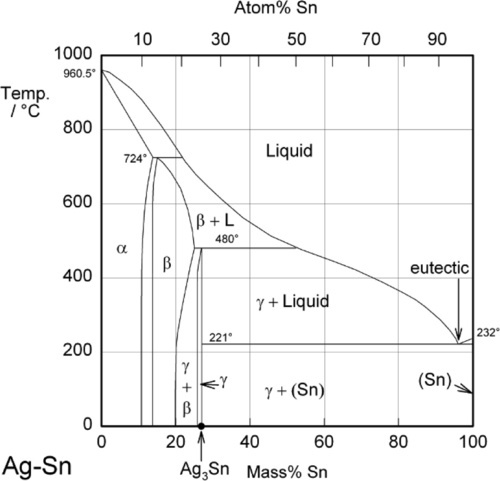
Most modern dental amalgam alloys are based on or derived from the intermetallic compound Ag3Sn, the γ-phase of the Ag-Sn system (Fig. 1.1).[1] In the early stages of development, when only Ag-Sn alloys were considered, this overall composition gave what seemed to be a balance between setting expansion (high Ag) and contraction (high Sn) as well as good mixing and handling properties, with good strength. It can be seen from the Ag-Sn constitutional diagram that the γ-phase has very narrow compositional limits, as befits the label ‘intermetallic compound’. Compared with that composition, an excess of Ag will lead to the appearance of the β-phase (~ Ag5Sn at its high-Sn phase field boundary), while excess Sn merely gives the solid solution of Ag in Sn, which is very nearly pure Sn.
•1.1 Ag-Hg
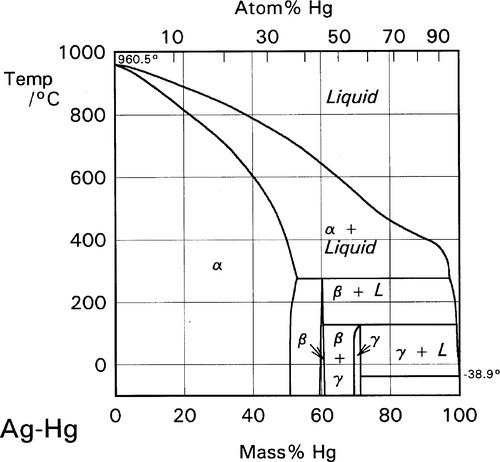
The initial reaction product of Ag with Hg is the so-called γ1-phase, approximately Ag4Hg51 (Fig. 1.2), as can be deduced by reading the diagram from the right at the level of room temperature. We can apply the thought-experiment approach of considering pure mercury to which is added a small portion of silver – effectively what happens as the alloy reacts when amalgam is mixed (cf. the zinc phosphate analysis, 9§5). This is an example where Ostwald’s Rule of Stages (8§2.6) applies quite nicely because of the presence of the highly diffusible, liquid mercury. We can be sure that γ-Ag-Hg is formed first at normal temperatures because we see from the diagram that it is stable in contact with liquid mercury – while that continues to exist. Equivalently, there is no phase field with the description β + Liq at temperatures below about 127 °C; β is therefore unstable with respect to liquid Hg, hence any silver added must react to give γ immediately. The second Ag-Hg phase, β1 (approximately Ag5Hg4), is expected to form in the presence of excess silver, that is when the Hg has been used up. But since this would be the result of a solid state reaction, it would consequently be expected to appear only very slowly at normal temperatures. We shall return to a consideration of this phase later.
•1.2 Hg-Sn
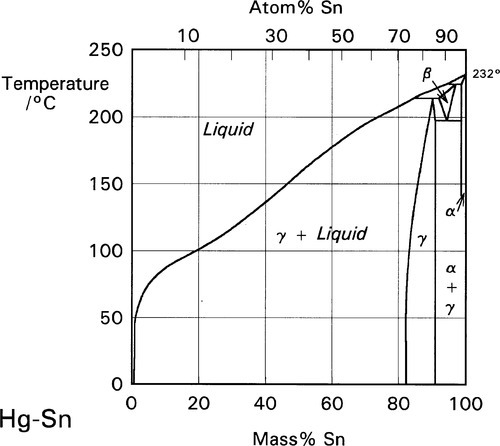
There is only one reaction product of Sn with Hg at normal temperatures, namely the γ-Hg-Sn phase (Fig. 1.3), which is given the label γ2 in the context of dental amalgam. This may have a wide range of compositions if only Hg and Sn are present, but in dental amalgam this phase seems to be best described as approximately HgSn7·6. This phase has been the focus of much attention from the point of view of strength, creep and corrosion. We will return to these points below.
•1.3 Alloy + Hg
The reaction products of Hg with pure γ-phase Ag-Sn alloy are just the same as with the pure metals, so that the basic setting reaction of such a mixture may be given as2:
< ?xml:namespace prefix = "mml" ns = "http://www.w3.org/1998/Math/MathML" />
It is worth emphasizing that, contrary to common statements, there is no evidence that Hg can dissolve in Ag3Sn to any measurable extent at the beginning or during the reaction. The decomposition of γ-phase Ag3Sn is the only consequence of its contact with mercury. Amongst the evidence for this is the failure to detect any transformed zone in the surface of particles of alloy in etched polished sections[2]. Notice that it does not matter whether such a composition is possible (such as by using high-temperature preparation techniques), only that it does not happen under normal conditions.
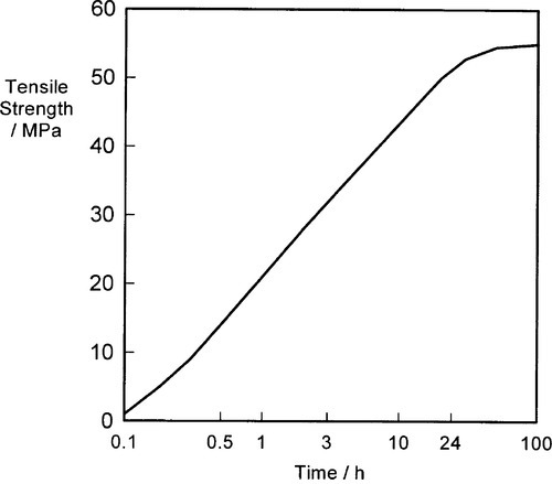
The conversion of the originally liquid Hg phase to a solid matrix, in which is embedded the remaining unreacted (or residual) alloy particle (assuming that there is present insufficient Hg for complete reaction of the alloy), constitutes the production of the composite-structured restorative material called dental amalgam, and is responsible for the development of its strength (Fig. 1.4).[3]
The reaction of β-phase Ag5Sn is essentially the same as for γ-phase but it occurs at a very much greater rate, although necessarily with different proportions of products:
If there were excess Sn in the original alloy this would, of course, merely produce more γ2-phase.
These reactions can be summarized in the (non-equilibrium) constitutional diagram shown in Fig. 1.5.[4] This is to be read by first drawing a line from the Hg apex to cut the Ag-Sn composition line at a point corresponding to the alloy of interest; that is, the line of constant Ag-Sn ratio, which must always be the case for mixing a given alloy with mercury. This Ag-Sn edge of the triangle, of course, corresponds to an isothermal section in Fig. 1.1 at about room temperature. Then, moving along this reaction line isopleth from the alloy composition point on the Ag-Sn edge, the consequences of slowly adding Hg to the mixture (or vice versa) may be deduced, again doing a thought experiment in the manner used for the discussion of zinc phosphate cement (9§5).
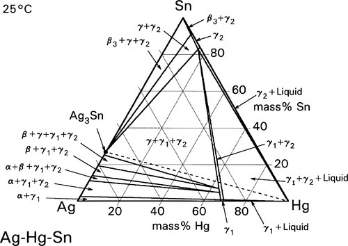
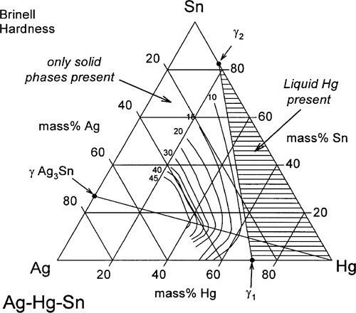
It can thus be seen that only mixtures with the phase description γ + γ1 + γ2 can be formed from using Ag3Sn, at least until all that γ has been consumed. There is then only a very narrow field corresponding to γ1 + γ2 to be crossed before liquid mercury remains unreacted in the mixture. The presence of a liquid phase causes a dramatic loss in strength and hardness. The effect of composition on Brinell hardness can be judged from Fig. 1.6, where the isopleth is drawn in, and on strength from Fig. 8.5[5].
•1.4 Cu
The addition of copper to the basic Ag-Sn alloy was found to improve the strength of the resulting amalgam, but too much (greater than ~ 6 mass%) led to excessive expansion on setting, which risked splitting the tooth or at least pain for the patient. Such alloys were accordingly deemed as not acceptable according to many national standards specifications on these products. The acceptable compositions are now referred to as low-copper alloys, for reasons that will become clearer shortly. As now the Ag-Cu and Cu-Sn systems make a contribution to the net constitution of the alloy, these two phase diagrams (Figs 12§3.1, 12§5.1) should be reviewed.
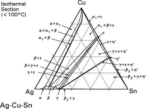
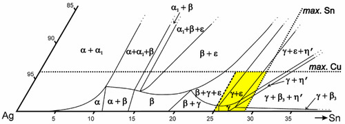
The room temperature isothermal diagram of the Ag-Cu-Sn system is given in Fig. 1.7, with the detail of the dentally relevant area shown enlarged in Fig. 1.8. In this latter figure the compositions corresponding to formerly ‘standardized’ and ‘acceptable’ alloys are indicated by the dotted lines. Notice that eight possible phase descriptions may apply to such an alloy at equilibrium. The Cu will be present in part in solid solution in the β and γ Ag-Sn phases. But, depending on its quantity and the amount of Sn in the alloy, either or both of the intermetallic compounds Cu3Sn (ε-phase) and Cu6Sn5 (η′) may be present. The solid solubility of Cu in β3-Sn is very small (see box).
Some Cu can be seen to be in solid solution in the γ-phase (about 1%). However, the solubility of Cu in the γ1-phase is appreciably lower (less than a third of the value), and so a Cu-Sn phase must form during the setting process, probably η’.
•1.5 Slow reactions
Additional reactions to those already outlined are, of course, possible when such alloys are mixed with Hg. The reaction rate of β- or γ-phase Ag-Sn with Hg is sufficiently fast that the γ2-phase is always formed initially, but Cu3Sn (ε-phase) and γ2 cannot exist together for long and the relatively slow reaction
must occur. This is at a relatively low rate because it is a solid state reaction. The rate is even slower than might be expected because these two phases will be distributed as small grains throughout the amalgam without necessarily touching, and all diffusion of metal atoms must be through other phases or grain boundaries. The Hg liberated from the γ2-phase partially reacts further with γ-phase alloy remaining (according to reaction 1.1), and partially is incorporated in the η′-phase in solid solution.
Because of this last behaviour, the composition of η′-phase in the matrix of a set amalgam does not correspond to Cu6Sn5, but because the crystal structures are indistinguishable, and there is no boundary formed between them either physically or in the constitutional diagram, they are one and the same phase. Such extra dissolved elements are frequent features of complex mixtures. Thus, it is known that both the γ1 and the β1 phases of a dental amalgam contain some dissolved Sn, somewhat more in the latter phase than the former. This has implications for structure, electrode potential and so on, but it does also mean that detailed stoichiometry calculations are difficult. All compositions given here (and elsewhere!) are necessarily approximations
In the long term (i.e. on a scale of years), the conversion of γ1 to β1 may occur in the presence of unreacted γ-phase alloy because this is thermodynamically required (cf. Ostwald’s Rule of Stages, 8§2.6):
As this latter phase is capable of holding a certain amount of Sn in solid solution, this may come from the γ-phase also. Under normal circumstances this is indeed a very slow reaction, and periods of several years at mouth temperature are required for the product phase to be detectable.
Only one other reaction is of significance in this system, and that is in the presence of excess Hg (in terms of the reaction with Ag-Sn phases), namely the decomposition of Cu-Sn phases to give the phase Cu7Hg6 (β2-phase) (see 28§6.5):
Ordinarily, however, β2 should not be detectable. If it is found it can be taken as an indicator of excess mercury in the original mixture. Naturally, γ-phase Ag3Sn will not then be detectable.3
•1.6 Importance of γ2
It will have been noticed that the γ2-phase in a set amalgam may be reduced in quantity, or even eliminated, by the presence of ε-phase Cu3Sn (reaction 1.3). This is a potentially valuable reaction for several reasons. With the exception of the very small amounts of zinc present in the alloy in solid solution (§2.4), tin is the most electropositive element present. In the γ2-phase it also has a high activity, making this the most electropositive phase, and hence the most easily corroded. Since the corrosion properties of a polyphase alloy system depend on the potential difference between the most and the least electropositive phase, the elimination of the γ2 would be expected to be a distinct improvement. The γ2-phase is also extremely weak and soft, deforming readily, and the strength of amalgam is thought to be limited by its presence. Thirdly, because it is so weak it is thought to contribute to the static creep of amalgam; this is the continuing deformation which is observed under loads well below the conventional yield point (1§11).
•1.7 Added Cu
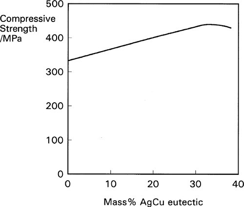
As has already been said, more than ~ 6% Cu may not be included in the so-called ‘conventionally’ formulated alloy because excessive expansion on setting results. However, if the extra Cu is incorporated in the form of a second alloy powder, mixed with the first (such a mixture of two powders is called an admixed alloy), the difficulty may be avoided. One such second alloy which has been found to be particularly effective is the eutectic of the Ag-Cu system; this corresponds to the composition 3Ag.2Cu (Fig. 12§3.1). Recall that this is a two phase alloy (α-Ag + α1-Cu solid solutions), and not a compound or single phase solid solution (hence the special way of writing its composition). It has the characteristic finely-lamellar structure (Fig. 12§3.7 b). The relevant reactions may be written together as:
Again, because this is a solid state reaction, it does not proceed very rapidly, but it may be essentially complete within a few days. The elimination of, or at least great reduction in the quantity of, the γ2-phase results in improved properties as indicated above, particularly in the compressive strength (Fig. 1.9). There will also be some direct reaction of the kind

This alloy system was not, however, designed on the principle of γ2-phase elimination. It was originally thought that, in the usual manner of composite structures, the incorporation of a very strong, stiff and hard alloy in the form of fine particles would impart these properties to the resulting amalgam. It was not for some time that the true reason for at least the major part of the improvement in strength was discerned. However, all alloy compositions in which there is substantially more than the previous limit of 6% Cu are now called high-copper, and thus also the amalgam made from them.
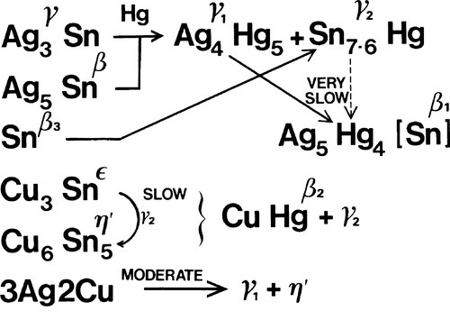
•1.8 Summary
The reactions of dental amalgam may be summarized as in Fig. 1.10. Unfortunately, there are now many variants on the market, having various modified compositions, some with extra elements such as palladium (Pd) and indium (In). In all cases it is a matter of affecting the ratios of reaction products, reaction rates, and detailed constitution and phase compositions. However, the basic phase description and setting reactions will be much the same. Nevertheless, the discussion above has treated the system as if it were more or less at equilibrium in both the initial alloy and the resulting amalgam. That this is far from the case will be shown. But first, in order that this be understood in context, it is necessary to indicate briefly alloy powder manufacturing methods to show how variation can come about.
§2 Alloy Powder Manufacture
The manufacture of an alloy for dental amalgam essentially consists of the melting together of the component elements to form a single phase, a liquid solution – the melt. This can then be cooled to form the solid which is then comminuted, that is, reduced to a powder. It is at the cooling stage that several possibilities arise for the constitution of the alloy, as detailed in §3. The oldest and most obvious comminution method is dealt with first.
•2.1 Lathe-cut
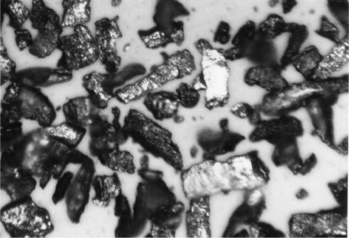
Pouring the melt into a cylindrical iron mould and allowing it to cool unassisted in air gives a solid ingot; typically this may be about 300 – 400 mm long by 50 mm diameter. This is then mounted on a lathe and turned to produce a very coarse powder. Amalgam alloys are fairly brittle, and the chips fragment readily as they stream from the cutting tool (see Fig. 20§3.2). The stub, where the ingot was gripped in the chuck, and a thin column of alloy that is not readily turned, can be remelted in a subsequent batch. The coarse powder is then ball-milled to reduce it to finer particles. This consists of tumbling the powder with large steel or ceramic balls in a large rotating pot, relying on the alloy’s brittleness for each particle to be crushed. Simply sieving, or now more conveniently air-elutriation (whereby a whirling column of air sorts powders by lifting the particles to different heights according to their mass), then yields a powder of the desired particle size range. These particles are necessarily irregular in shape (Fig. 2.1). Of importance is the fact that they are heavily cold-worked.
When dental silver amalgam was first invented it was the practice to use a file to create the powder from a solid piece of metal, such as a silver dollar coin. The term filings was and may still be applied to the powder prepared by turning and ball-milling.
•2.2 Spherical
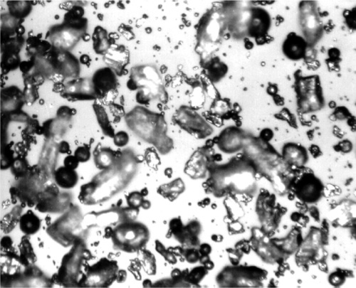
Clearly, the above process is time-consuming and requires a great input of energy at the turning and ball-milling stages, much of which is wasted as heat. Spraying from the melt, or atomization, avoids both of these stages altogether. The molten alloy is squirted through a small jet into a non-oxidizing atmosphere, whereupon the stream breaks up into fine droplets which, aided by very high surface tension and low viscosity (compare Table 18§2.1), rapidly assume a spherical shape (Fig. 2.2). The very high surface area causes very rapid cooling to solidification, with no time for an equilibrium structure to be developed, but the resulting powder then only needs sorting to give the desired product. These materials are therefore called spherical particle amalgam alloys, or simply (but confusingly) ‘spherical alloys’ (when mixed with Hg they give ‘spherical amalgams’!). By way of contrast, the mechanically-comminuted types are called ‘conventional’, a term which embraces the compositions near Ag3Sn, but which is rapidly becoming nonsensical as both composition and presentation now vary so widely in commonly-used commercial products. ‘Lathe-cut’ is a preferable term.

The Ag-Cu eutectic particles added to certain high-copper amalgam alloys is invariably produced by spraying from the melt. This is the only practical way of producing such powders in bulk because the eutectic is so very tough (characteristic of eutectic alloys); machining such as lathe-turning is virtually impossible.
Even faster cooling is possible. By squirting the melt directly onto a high thermal conductivity surface, cooling rates measured in millions of degrees per second can be attained. This may be done on a rapidly rotating aluminium drum, for example. Some (non-dental) alloy systems produce metallic glasses when they are treated in this way. With amalgam alloys, however, merely a very fine-grained and highly-strained structure is formed in the ribbon of metal, and this fragments readily to a powder. The crystal structure is also very imperfect, and this causes certain problems, discussed below. No commercial exploitation of this is known at present, although as a method it has been investigated extensively.
•2.3 Blending
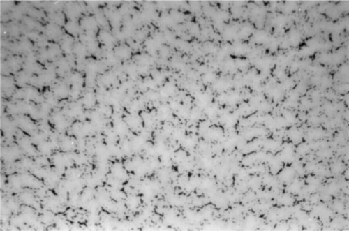
The manufacturing techniques described above result in powders that have different internal structures and different particle shapes. The phase constitution of the alloy is of great importance to the behaviour on setting, as will be detailed in the next section, and this depends on the composition to a large extent. It may be that a single alloy with a given composition has some undesirable feature. In addition, the particle shape affects the ‘feel’ of the material when it is being packed; this is dealt with in §4.1. Sometimes the desired behaviour and properties cannot be obtained by preparing a powder from just one composition melt using just one method. Sometimes it is only a matter of creating a product which is patentable, perhaps avoiding a rival’s patent. In each case, however, blends of alloys may be used. That is, powders of different composition, thermal history and particle shape may be mixed to create the commercial product. There are indeed many variations possible and that have been sold. Whilst these blends may introduce differences from the descriptions in this chapter in various ways, they do not seriously affect the principles described here. They are neither good nor bad in any general sense, and such products must be judged on properties such as strength, expansion and cost. Such alloy products may be described as admixed, with the implication of the admixture being in lesser amount than the ‘basis’ alloy powder (Fig. 2.3).
•2.4 Contaminants
Whatever the technique subsequently used to create the powder, all processes must first melt the alloy components. Tin and copper, however, oxidize in air, and molten silver-rich alloys may dissolve large quantities of oxygen from the air, encouraging the oxidation of the Cu and Sn. The composition changes that then occur make such oxidation undesirable. Even if the metals are melted under an inert gas blanket, such as argon, it is difficult to exclude air completely, and even the original silver ingots may contain oxygen from their previous melting. Sulphur is also frequently present as an impurity in many metals. Such contaminants as these may also change the properties of the resulting alloys. However, both oxygen and sulphur can be readily scavenged from the melt by the addition of a small quantity of a more electropositive metal, and zinc is convenient: it is both cheap and reactive. Typically, about 2% by mass may be added to the melt, although it is expected that much of this will be oxidized or volatilized and therefore lost from the system, reducing the amount left in the final alloy, perhaps to very low levels. This remaining zinc will be present in solution in the γ-phase, and end up in the γ1-phase after reaction.[6] These deoxidized alloys are typically less brittle than their oxygen-containing counterparts, and this increased ductility is associated with a more easily polished and potentially tougher amalgam that has been reported to perform better in service.[7]
A variety of other contaminants may be present, generally at low concentration, such as Sb, Cd, In, and Pb,[8] according to the nature of the source ores for the principal components and the purity (price!) of those component metals as bought. Generally, these will be present in solid solution in the alloy, and thus affect mechanical properties. Their fate in a set amalgam is unreported.
§3 Cooling Rate and Constitution
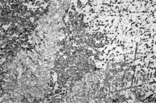
As previously discussed (12§1), the rate of cooling from the melt has profound effects on the phase description of the resulting solid, which may be very far removed from that expected at equilibrium; this applies equally to amalgam alloys. For moderately fast cooling, an alloy corresponding closely to an overall composition expected to give only γ + ε, with less than 6% Cu (cf. Fig. 1.8), may in fact show very clear coring.
The first phase to form is β-Ag-Sn, in the form of dendrites (branching, tree-like crystals), embedded in a γ-phase matrix which will have frozen later (Fig. 3.1).[9] This can be seen to be required by tracing the cooling of Ag3Sn alloy in Fig. 1.1: the β + Liquid field is the first to be encountered. Appropriate etching of a polished section of such an alloy specimen reveals a fine dispersion of eutectic (Fig. 3.2), the material last to freeze (cf. Fig. 1.1). This material consists of a matrix of β3 (nearly pure Sn) containing an extremely fine dispersion of γ-phase, too small to be detectable at the present scale.
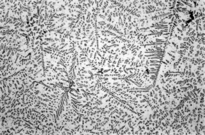
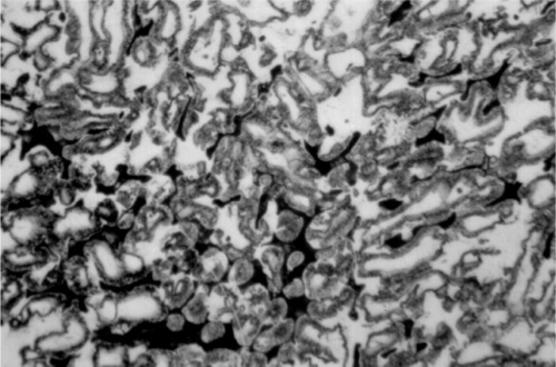
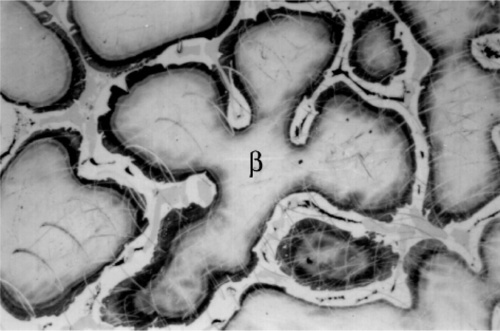
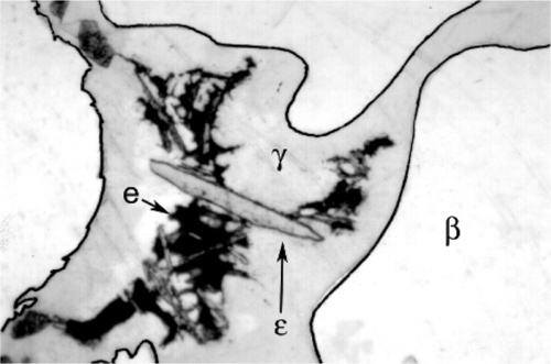
Somewhat slower cooling results in more prominent β-phase dendrites (Fig. 3.3) and coarser eutectic (Fig. 3.4), although the Cu-Sn phases (if present) remain relatively fine-grained and well dispersed. Very slow cooling produces very large dendrites (Figs 3.5, 3.6) which are expected to show a gradation of Ag-content according to the variation of the composition of the liquid as solidification proceeds. This has shown up in the etched section by variation in the colouration (viz. low Ag ≡ dark staining). Note that the dendrites are still all β-phase structure; it is because that phase field is broad (Fig. 1.1) that there is a wide composition range possible. Surrounding each dendrite is a layer of γ-phase (Ag3Sn) which has not been etched; embedded in this are grains of ε-phase as well as eutectic.
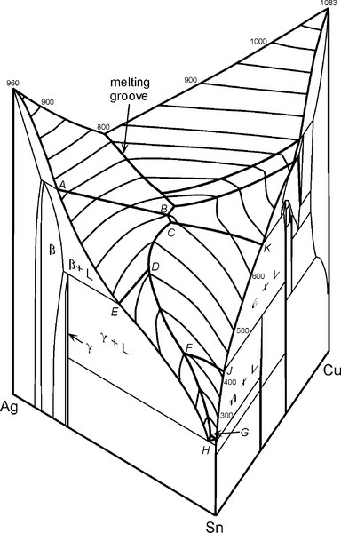
For a full appreciation of the range of possible phase descriptions, reference must be made to the Ag-Cu-Sn ternary diagram (Fig. 3.7), and in particular to the melting grooves on the liquidus surface. This kind of diagram can be imagined as a part of a hilly landscape, where the stream beds are the exact topographical equivalent of the melting grooves. The main melting groove is the locus of the eutectic point for a series of pseudobinary (vertical) sections through the prism-shaped body. The path starts at the eutectic for the Ag- Cu system, and then goes through the points B, C, D, F, G, H. The ‘tributaries’ correspond to other phase changes. In a binary alloy the last liquid to be present when it is cooling and segregating is the eutectic. Similarly, in a three component system the liquid has a composition which follows the liquid us surface, but now it is for a line corresponding to the path of steepest descent on the ‘hillside’. It does this until it meets a melting groove, and then the composition follows that path – because this is now the path of steepest descent. The liquid composition therefore follows the track that a ball would take if placed on the surface and allow to roll.
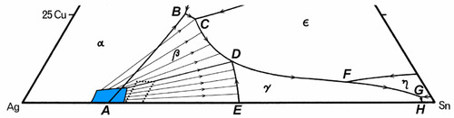
A partial map of the melting grooves for the dentally-relevant part of the Ag-Cu-Sn system is shown in Fig. 3.8. The phase label that is shown in a region is that of the solid to form from a liquid composition lying within that area, that is, with the melting grooves as boundaries. If the liquid composition lies exactly on boundary (i.e. is in the melting groove), the two solid phases shown either side of the line at that point will form simultaneously – as in a binary eutectic. Once a liquid composition and its temperature correspond to lying in a groove, the liquid composition must follow that track all the way to the eutectic (H). Also shown are a few of the kind of tracks expected for the appropriate isothermal tie-lines (see Fig. 8§4.2) which pass through the composition range area of dental interest (dotted) – bearing in mind that these are projected onto the plane. Briefly, these tie-lines connect the solid forming at any instant with the liquid from which it is forming, the conjugate phases, in the same way as tie-lines in a two-component diagram (Fig. 8§3.7). Thus, picking a composition for the alloy melt, as solidification and segregation is occurring the composition of the liquid varies, following first the tie-line track until a melting groove is reached, and then following that groove path.
Following those rules, studying these diagrams shows the following possible sequence of reactions for a dental amalgam alloy on cooling from the melt at a rate too fast for equilibration of the solid to occur, i.e. normal rates of cooling:
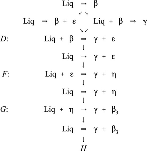
Here, H is the final Ag-Sn eutectic, which is the eutectic for the overall ternary system. This scheme can be understood as a step by step chain of events representing the various stages of the segregation process. Thus, the first solid to form is always β, and the composition of the liquid moves steadily away from the starting composition, following a tie line, until it reaches the melting groove. Remember that the temperature is falling for this to occur and therefore the track on the liquid us surface (Fig. 3.7) is ‘downhill’, following the path of steepest descent at any point.
What happens next depends only on whether the Cu content of the initial melt was high enough that the melting groove is reached above (i.e. higher Cu concentration) or below the junction point D; this is the point where two paths are shown in the diagram 3.1. If above, then simultaneous freezing of β + ε occurs; if below, then there is a peritectic reaction with existing solid to produce γ. Either way, because these two melting grooves are confluent, the next step is common: the β phase becomes unstable, and reacts with the liquid while γ + ε is freezing out. Downhill/>
Stay updated, free dental videos. Join our Telegram channel
VIDEdental - Online dental courses


