11
3D Orthodontic Diagnosis and Treatment Planning
Introduction
In the 20th century, the cephalogram was a pioneering advance that led to many fundamental insights into the changes in the neurocranium and face during growth and with treatment. This imaging approach also became a standard part of orthodontic records for confirming diagnosis and treatment plans, as well as evaluating treatment outcomes (Broadbent, 1931). However, cephalograms provide only a compressed two-dimensional (2D) view of the complex three-dimensional (3D) craniofacial structures. The need for 3D information for orthodontic purposes has been evident for decades, and several attempts have been made to achieve this goal (Savara, 1965; Solow, 1970; Baumrind & Frantz, 1971; Hixon, 1972; Ricketts, 1972; Goldberg, 1973; Maganzini, 1974; Thurow, 1981; Bookstein, 1982; Vig, 1982; Baumrind et al., 1983a, 1983b; Grayson et al., 1988; Bookstein et al., 1991; Altobelli et al., 1993). More recently, the introduction of relatively low cost, high resolution, cone beam computed tomography (CBCT) has provided researchers and clinicians with the tool needed to acquire those images in 3D (Kau et al., 2005; Palomo et al., 2005; Kapila et al., 2011). Given its attributes, CBCT imaging may become the 21st century’s equivalent of what the cephalometer was for orthodontics in the 20th century.
CBCT provides more diagnostic information, unobstructed views of anatomy, relative density information, and an easy-to-understand complete radiographic view of the orthodontic patient. With regard to image quality, completeness, and versatility, CBCT has clear advantages over the cephalometer; however, its higher ionizing radiation results in a benefit/risk ratio that is not always weighted positively toward CBCT. In keeping with the “as low as reasonably achievable” (ALARA) principle, if ionizing radiation were reduced below that of current orthodontic radiographic series, it is possible that orthodontists would take CBCT scans on most if not all of their patients, and the cephalometer would become obsolete.
The radiation received by the patient from a CBCT scanner for a large field of view (FOV), which often is preferred for orthodontic imaging, can be different depending on the scanner used (see Chapters 2 and 3). Although these are low doses relative to medical radiographic imaging, there are substantial differences in radiation doses between different CBCT scanners even when used for the same purpose (Pauwels et al., 2012; see Chapters 2 and 3). The current ionizing radiation dose of CBCTs could be lowered further by technique standardization, the use of optimized and customized imaging protocols, and improvements of CBCT scanners as discussed elsewhere in this book (see Chapters 2 and 5). Thus, just as there are specific computed tomography (CT) protocols for different radiographic exams in medicine, rather than using a standardized CBCT protocol for every orthodontic patient, specific protocols that provide the desired images and may help lower the radiation can be developed for each patient or procedure. CBCT scanner optimization, which could be achieved by modifications to the hardware and/or software also could help to lower ionizing radiation doses. These modifications include utilization of pulsed mode radiation and the optimization of radiation arc, post-scan adjustments, scanning time, receptor sensitivity, numbers of rotations, collimators, and filters (see Chapters 2 and 5).
The utility of CBCT in orthodontic diagnosis is constrained partially due to the lack of universally acceptable protocols and availability of reproducible and quantifiable analyses. The purpose of this chapter is to provide insights into the protocols that we have developed at Case Western Reserve University (CWRU) for CBCT imaging of orthodontic patients and approaches for qualitative and quantitative analyses of these images to extract important diagnostic information. This chapter, therefore, provides one example, but not the only approach, of utilizing CBCT in the evaluation of craniofacial structures that could be useful in orthodontic diagnosis and treatment planning. Variations of these protocols and approaches and their customization to complex cases also are presented elsewhere in this book (see Chapters 1, 8, and 23).
CBCT’s Role in Orthodontic Diagnosis and Treatment Planning
The primary purpose of imaging is to answer questions that otherwise cannot be addressed clinically or to confirm or rule out what was found during a clinical exam. Thus CBCT, like other radiographic examinations, offers another important tool in our armamentarium that, depending on the information required, may or may not be useful. In order to decide which tool to use, it is essential to understand what this approach has to offer and to know how to use it. CBCT technology offers a range of options. Current scanners offer a multitude of image sizes and several options for mA, kVp and even voxel size (see Chapter 2). We have evolved from the time that a radiograph was just a radiograph; now the image can be customized to fit our needs. More important, with all these tools at our disposal, the clinician needs to know which imaging protocol would enhance the understanding of the patient’s clinical findings best. Despite these advantages of CBCT, the initial clinical exam remains the most important step in orthodontic diagnosis. Such direct evaluation allows the clinician to use three senses: listening to the patient’s description of his or her condition and main goals for treatment outcome, assessing the face and dentition along with facial animation, and analyzing function including the movements of the temporomandibular joints (TMJs) and the intra- and extraoral musculature. This evaluation, together with a complete review of the medical and dental history and assessment of treatment needs and wants, will determine which additional diagnostic information may be required, including which if any imaging modality is necessary to confirm the findings, help in treatment planning, and rule out any current or potential problems during treatment. Thus, even though radiographs, whether 2D or 3D, may be used to refine diagnosis and help corroborate treatment plans, no imaging modality is a substitute for the clinical examination of the patient.
A skilled clinician will use diagnostic tests such as cephalometric analysis to confirm the diagnoses. It is common to use quantitative methods to supplement subjective evaluation because this leads to more consistent diagnoses and, subsequently, to more consistent treatments. For example, the lateral cephalometric technique enables the clinician to characterize skeletal and dentoalveolar morphology of patients in the midline. This information improves our understanding of the underlying basis of malocclusions with reference to midline structures in both the sagittal and vertical planes. All of the standard lateral cephalometric analyses answer five basic questions about the patient’s midline skeletal and dentoalveolar relationships, namely:
- What is the position of the maxilla with respect to the cranial base?
- What is the position of the mandible with respect to the cranial base?
- What is the position of the maxillary teeth with respect to the maxilla?
- What is the position of the mandibular teeth with respect to the mandible?
- What are the vertical proportions of the facial thirds?
Norms have been developed for each of these five anatomic relationships that, with some exceptions, aid the clinician to characterize the malocclusion and to arrive at the most appropriate strategies for correction of the discrepancies. Although normative information for CBCT analysis may be useful, the need for CBCT norms may not be as critical as that for the cephalogram because a CBCT image is more akin to the patient than the cephalogram: unlike in the case of a cephalogram, the anatomy viewed in a CBCT is unobstructed, accurate, and distortion-free while also being able to provide all the information available from cephalometry. For example, the precise position of impacted teeth, their contact with other teeth and position, and alignment of roots do not require the determination of distances or angles in order to be helpful (see Chapters 15 and 16). The 3D and/or multiplanar visualization in such clinical situations may be adequate for the experienced clinician to derive an optimal treatment plan. The availability of information from these additional views represents some of the many situations in which CBCT can contribute to modification to an orthodontic treatment plan by providing information not accessible by any other available means. While these clinical scenarios may not require CBCT norms for extracting important diagnostic information, several other situations exist in which CBCT norms may be useful for treatment decision.
The CWRU Comprehensive CBCT Analysis
At CWRU, we currently have two different CBCT scanners that, in addition to having true 2D cephalometric and panoramic radiographic capabilities, provide up to 10 possible FOVs. Our CBCT scanners have been optimized with decreased radiological settings in combination with image quality optimization, which substantially reduces the amount of ionizing radiation exposure (Kwong et al., 2008; Palomo et al., 2008). However, the approaches to analyzing a CBCT and making the best possible use of the information it provides has not been standardized yet. For educational purposes and to facilitate the transition from 2D to 3D imaging, we have partially standardized approaches to managing and using 3D CBCT volumes. In the past, the orthodontic electronic records for our patients included the standard three extraoral photos, five intraoral photos, a panoramic radiograph, and a cephalogram. With the inclusion of the CBCT volume, there are additional images to include in the records and review on the computer. The volume can be viewed in both 3D and multiplanar modes. The multiplanar reconstructs (MPRs) incorporate axial, coronal, and sagittal views with slices that can be as thin as the voxel size. The 3D view can be visualized from every direction by rotating it; however, this rendering is not truly a 3D image since it is displayed on a computer screen instead of as a holographic representation. The 3D displays also can appear different when using different software packages. Software image filters can be applied to create a smoother image, and several operator-controlled features allow the display of different density ranges that, depending on the settings, can show the same areas either covered or uncovered by bone. Due to display inaccuracies and inconsistencies in image filters, the most reliable and consistent method for analyzing a CBCT image uses the multiplanar mode.
Image Management Protocol and Obtaining Standardized Views
The CWRU imaging protocol starts with importing the CBCT volume into the patient’s electronic chart. This is important because it allows quick access of the complete 3D volume during appointments. Even though the complete 3D volume is imported into the patient’s file, there still is value in creating standardized views that represent different areas of the craniofacial complex and can be used to track progress or outcome assessment.
In order to create different views in a standardized way, the first step is the CBCT volume orientation within the software. Unlike cephalograms, a CBCT volume does not have rigid orientation hardware such as ear rods and nasion rests available during imaging. Also unlike cephalograms, a 3D image needs to be oriented in all three planes of space. Precise orientation of the volume is necessary in order to assess asymmetries and deviations accurately from normality while going through the MPR images.
Landmarks and Plane
Although other volume orientation methods are available (see Chapter 8 for an example), the CWRU orientation method uses five biologically relevant anatomical structures and one plane (Wu et al., 2012). The structures, used together with a brief rationale on their selection, are as follows and are depicted in Figure 11.1.
- The optic foramina are bilateral structures located in the sphenoid bone. The optic nerve along with the ophthalmic artery passes through these structures. The center of this and the other two foramina (listed below) are found by visual inspection as they enter the sphenoid bone and the x, y, and z coordinates of these points are recorded.
- The foramina ovale also are bilateral structures located in the posterior and lateral portion of the sphenoid bone.
- The foramen cecum is a midline structure located where the frontal bone articulates with the ethmoid bone.
- The McRae’s plane is located in sagittal view and is defined as a line drawn from the anterior margin of the foramen magnum (basion) to the posterior border (opisthion). The McRae’s plane commonly is used in neurosurgery as a stable reference for orienting the head in the sagittal plane. It also illustrates the degree of deformity and aids in surgical decision making with regard to fixation and stabilization (Goel, 2004). Aligning the McRae’s plane prevents superior and inferior tilting of the head at the time of surgery.
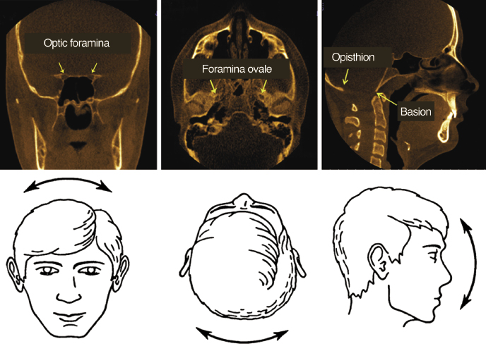
Method for Orienting the Head in Three Planes of Space
The coronal view is used to align the centers of the left and right optic foramina to correct any left or right tilt of the volume (Figure 11.1A). The axial view is used to align the centers of the left and right foramina ovale to correct any rotation of the volume (Figure 11.1B). The sagittal view is used to correct for superior and inferior tilting of head by aligning the axial plane to overlap with the McRae’s plane (Figure 11.1C).
Capturing the Views
The next step is to create different cuts or views of the volume necessary to synthesize our findings. Instead of two images (cephalogram and panorex), we now create 30 different views from a CBCT as listed below.
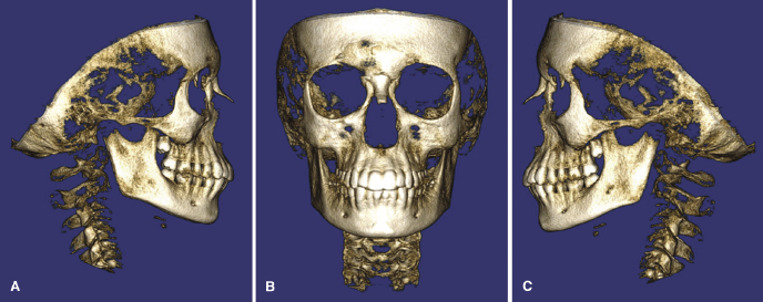
Right, Frontal, and Left Solid Views
These three views mimic the extraoral photographs, but show skeletal tissue instead (Figure 11.2). The display settings used do not permit transparency and, therefore, aid in the visualization of root coverage and bone anatomy. The soft tissue outline is not viewed often in these images.
Right, Frontal, and Left Side Transparency Views
These three views are similar to the ones depicted in Figure 11.3,/>
Stay updated, free dental videos. Join our Telegram channel
VIDEdental - Online dental courses


