Mandibular single dentures are not common. However, the same principles apply. Many prosthodontists believe mandibular single dentures cause the mandibular ridge to resorb rapidly due to the extra force exerted by the maxillary natural teeth. This is probably true, particularly in those individuals with clamping habits (bruxism) but other factors may influence the retention of maxillary teeth.
The following illustrations show the construction of a maxillary single complete denture. Compare these procedures to those for complete maxillary and mandibular dentures as you progress.
Figure 1 This patient has a good maxillary ridge. Note the difference in the length of the maxillary tuberosities.
Figure 2 The patient’s mandibular arch.
Figure 3 The patient’s mandibular arch has been restored with a removable partial denture. This is a pre-existing appliance which has been in use for several years. Now, refer to Figure 1 and correlate the appearance of the maxillary arch with the remaining mandibular natural teeth. You can see that the shorter maxillary tuberosity opposes the existing molar. The larger right tuberosity is most likely due to the action of the maxillary denture being tipped by the mandibular anterior teeth and the lower left molar, causing the right tuberosity to elongate.
When patients have difficulty wearing a single complete maxillary denture, always inspect the mandibular arch. A complete lower dentition is usually essential to provide adequate retention for a maxillary single denture. Otherwise, the denture will tip and lose retention whenever the teeth are brought together. The enlargement of the tuberosity as seen in Figure 1 will occur even if a partial denture is in place if the partial denture is not maintained and/or the resin teeth on the mandibular partial denture wear and do not provide adequate occlusal support.
Figure 4 Proper trays are selected to make a preliminary impression of the maxillary arch and an opposing cast of the mandibular arch.
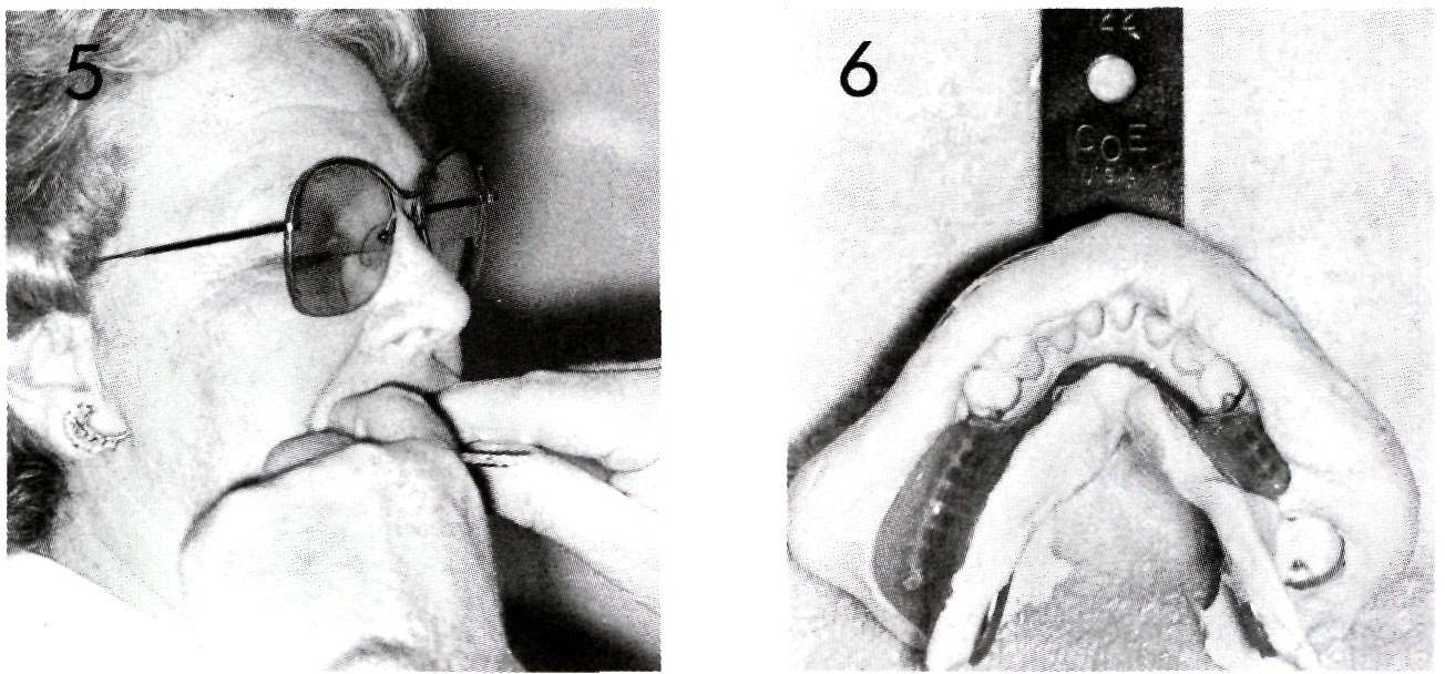
Figure 5 The mandibular impression is being made.
Figure 6 The mandibular partial denture stayed in the impression when it was removed from the mouth.
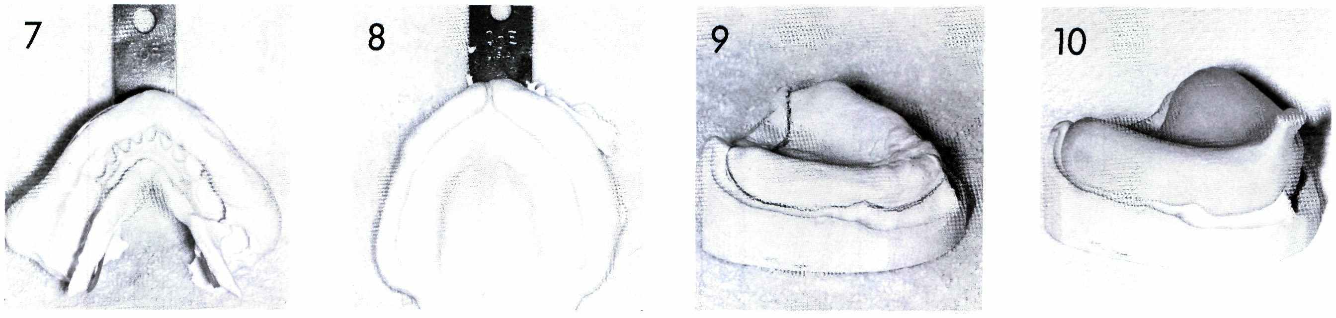
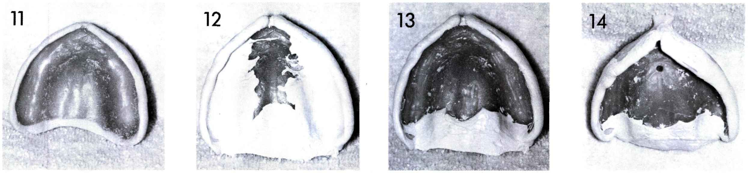
Figure 7 The mandibular removable partial denture has been removed from the impression and returned to the patient. The impression is now ready to be poured.
Figure 8 The maxillary preliminary impression is shown as it appeared when it was removed from the mouth.
Figure 9 The outline for the custom tray has been placed on the cast made from the preliminary impression. (Refer to Section 3)
Figure 10 A custom tray for the maxillary arch has been made. The same procedures are used as described in Section 3.
Figure 11 The wax shim or spacer placed in the maxillary custom tray may vary in configuration depending upon the desires of a particular dentist. Some dentists prefer to have their trays made without any shim.
Figure 12 Impression techniques vary among dentists and from region to region. This illustration shows the results of border molding, a procedure which defines the border or edge of the impression and the subsequent denture. The material used in this illustration is a heavy bodied zinc oxide-eugenol paste but other materials such as modeling plastic, specially made waxes, or some modified resin materials may be used.
Figure 13 The border-molding material has been removed from the tissue bearing areas of the impression. Note that some material has been left in the posterior palatal seal area which will help key the denture in place when the impression is made.
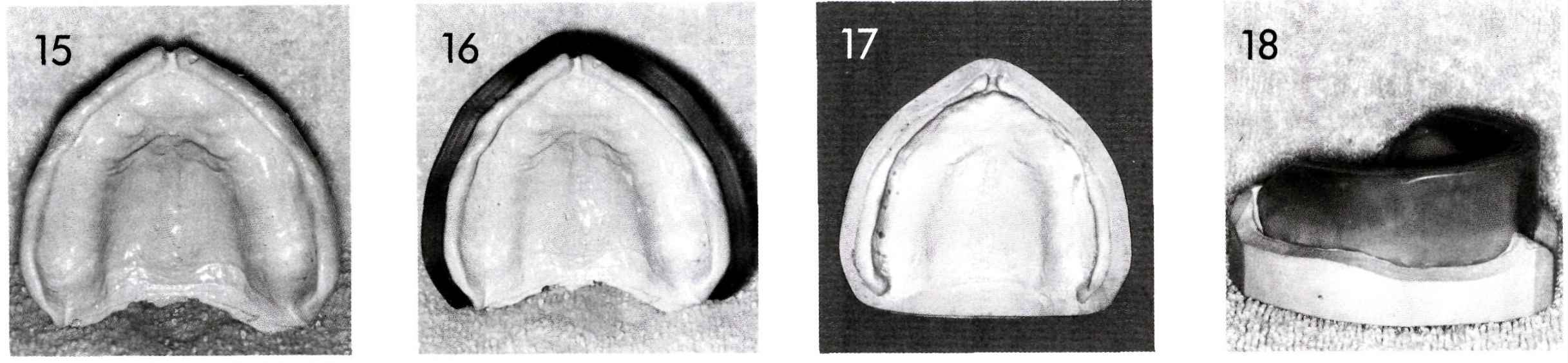
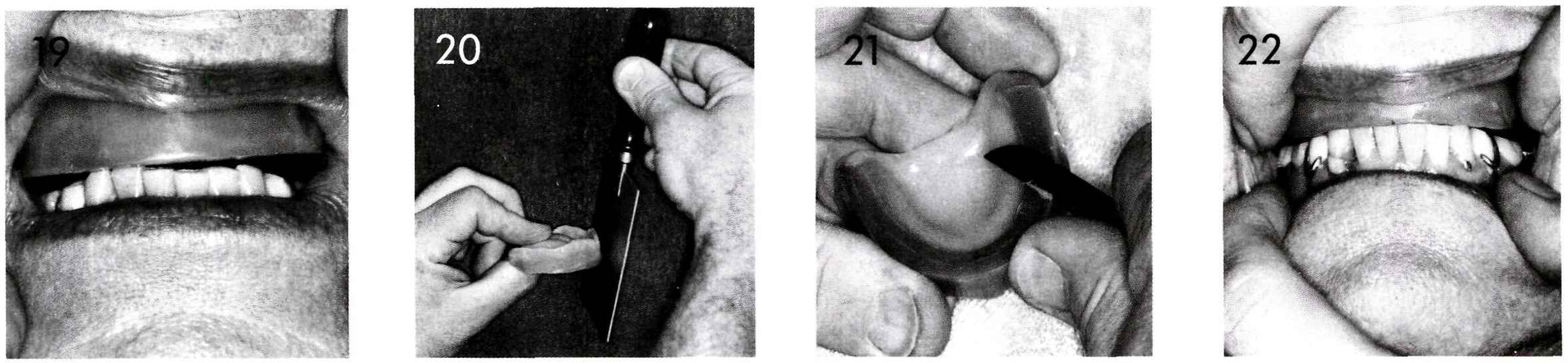
Figure 14 A vent hole is placed in the tray. This serves to relieve pressures which may build up in the palatal area and may distort the impression.
Figure 15 The completed impression. The steps in making this impression are included to demonstrate that often a simple looking impression is proceeded by precise handling of dental materials through several steps.
Figure 16 The impression is prepared for pouring. The same procedures are used in pouring this cast as described in Section 4.
Figure 17 The completed master cast.
Figure 18 A baseplate and occlusion rim have been made on the master cast. Refer to Sections 5 and 6 for the complete technique.
Figure 19 At the third patient visit, the maxillary occlusion rim is placed in the mouth and observed to see what changes need to be made.
Figure 20 The facial surface is adjusted by using a warm hotplate.
Figure 21 The anterior portion of the occlusion rim is reduced.
Figure 22 The occlusion rim has been adjusted so that the anterior teeth touch lightly and the correct vertical dimension has been achieved. Note the open space in the posterior region which will be filled subsequently with a soft wax.
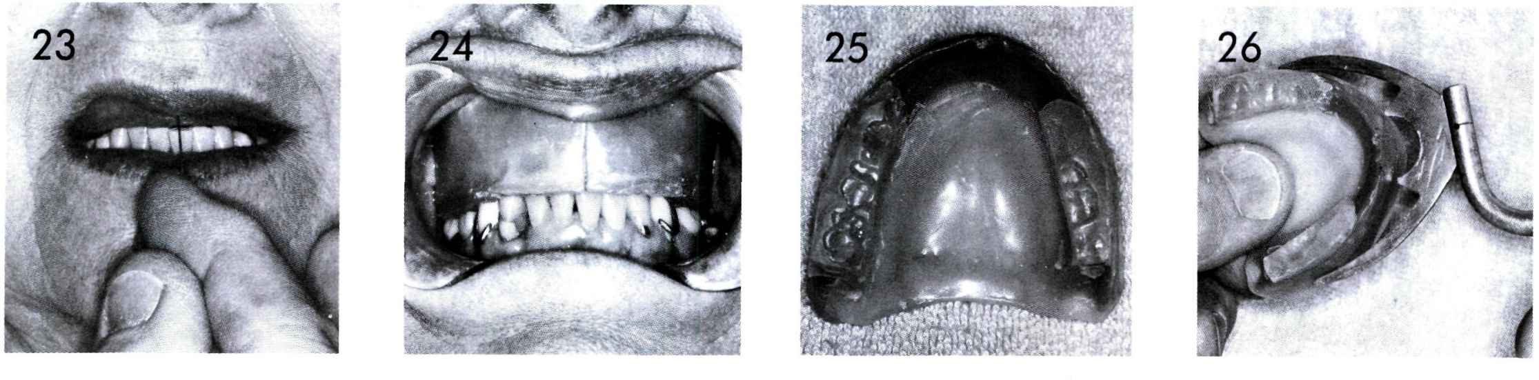
Figure 23 The center line is marked on the maxillary occlusion rim with an instrument. Note that the center line coincides with the center of the patient’s face and not with the center of the lower anterior teeth. This situation occurs quite often.
Figure 24 An occlusal index or interocclusal record is made by placing warm soft wax on the posterior region of the occlusion rim and having the patient close in centric relation until the mandibular anterior teeth barely touch the wax occlusion rim. After the soft wax cools, it is trimmed so that only the occlusal portions of the mandibular teeth remain in the index. This permits the occlusion rim with the occlusal index to be replaced in the mouth for verification of the correct occlusal relationships.
Figure 25 This illustrates the occlusal indexes left in the posterior region maxillary occlusion rim. If you refer to Section 7, you will see that when complete dentures are made for both arches the occlusal index is made on the mandibular occlusion rim. In this instance, the occlusal index is made on the maxillary occlusion rim because the occlusal plane is determined by the lower natural teeth and existing removable partial denture.
Figure 26 A face-bow transfer is made in much the same manner as for complete dentures. The bite fork is attached to the occlusion rim by heating the bite fork and placing it into the occlusion rim.
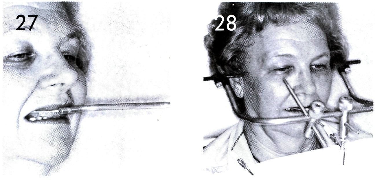
Figure 27 The occlusion rim with attached bite fork is placed in the patient’s mouth and the patient instructed to close with only enough force to maintain the maxillary occlusion rim in place.
Stay updated, free dental videos. Join our Telegram channel
VIDEdental - Online dental courses


